AIR CONDITIONING SYSTEM (for Automatic Air Conditioning System) SYSTEM DESCRIPTION
-
GENERAL
-
The air conditioning system has the following features:
-
An automatic, dual-control air conditioner system comprising front/rear independent temperature control is used.
-
In accordance with the temperature set using the temperature control switch, the air conditioning amplifier determines the outlet temperature based on the input signals from various sensors. In addition, corrections are made in accordance with the signals from the water temperature sensor to control the outlet air temperature.
-
Controls the blower motor in accordance with the airflow volume determined by the air conditioning amplifier based on the input signals from various sensors.
-
Automatically changes the outlets in accordance with the outlet mode ratio that is determined by the air conditioning amplifier based on the input signals from various sensors.
-
Based on the signals from the ambient temperature sensor, this system calculates the outside temperature and indicates it in the multi-information display.
-
The left/right independent temperature control and neural network control make air conditioner control available to suit the persons in the driver seat and in the passenger seat.
-
The Positive Temperature Coefficient (PTC) heater system contains a PTC heater that heats the air that has passed through the heater core to ensure the proper heater performance.
-
Turns the rear defogger and outside rear mirror heaters on for 15 minutes when the rear defogger switch is pressed. Turns them off if the switch is pressed while they are operating.
-
Checks the sensors in accordance with the operation of the air conditioner switches.
-
The air conditioning amplifier has the function of controlling the indicator lighting.
-
When a high load is applied to the EPS system, the EPS ECU will send a signal to the air conditioning amplifier. After receiving the signal, the air conditioning amplifier may turn off the rear defogger, front deicer, and seat heaters.
-
-
-
MODE POSITION AND DAMPER OPERATION
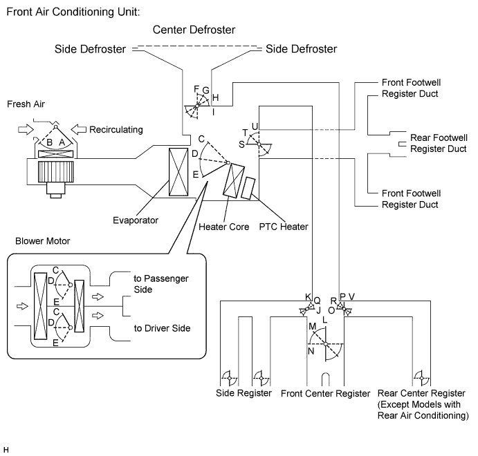
Control Damper Control Position Damper Position Operation Air Inlet Control Damper FRESH A Brings in fresh air RECIRC B Recirculates internal air Air Mix Control Damper
(Left/Right Independent Control)
Driver and Front Passenger Side MAX COOL to MAX HOT
(TEMP. SETTING 18 to 32°C (65 to 85°F))
C, D, E Varies mixture ratio of fresh air and recirculation air in order to regulate temperature continuously from HOT to COOL Mode Control Film Damper Driver and Front Passenger Side 
FACE
I, J, L, O, U Air blows out of center registers and side registers. 
BI-LEVEL
I, M, Q, R, T Air mainly blows out of center registers, side registers, and footwell register ducts. 
FOOT
H, K, N, P, S Air mainly blows out of front and rear footwell register ducts.
In addition, air blows out slightly from front and side defrosters, and side registers.

FOOT/DEF
G, K, N, P, S Air mainly blows out of front and side defrosters to defrost windshield. Air also blows out from front and rear footwell register ducts, and side registers. 
DEF
F, K, N, U, V Air blows out of front and side defrosters and side registers to defrost windshield. 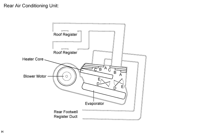
Control Damper Control Position Damper Position Operation Air Mix Control Damper MAX COOL to MAX HOT TEMP. SETTING 18 to 32°C (65 to 90°F) D, E Varies mixture ratio of fresh air and recirculating air in order to regulate temperature continuously from HOT to COOL Mode Control Film Damper FACE
A Air blows out of roof face ducts. BI-LEVEL
B Air blows out of roof face ducts and rear foot ducts. FOOT
C Air blows out of rear foot ducts. -
AIR OUTLET AND AIRFLOW VOLUME
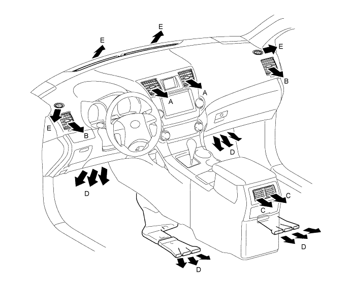
Air Outlet Mode Air Outlet Position Symbol A B C D E Center Face Side Face Foot Footwell Defroster FACE 
X X X BI-LEVEL 

X FOOT X 
FOOT/DEF X DEF X X X Tech Tips
The size of the circle ○ indicates the proportion of airflow volume.
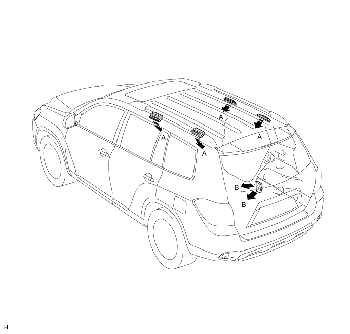
Air Outlet Mode Air Outlet Position Symbol A B Side Face Rear Foot FACE X BI-LEVEL FOOT X Tech Tips
The size of the circle ○ indicates the proportion of airflow volume.