POWER STEERING SYSTEM EPS Warning Light Circuit
DESCRIPTION
If the power steering ECU detects a malfunction, the P/S warning light comes on. At this time, the power steering ECU stores a DTC in its memory.
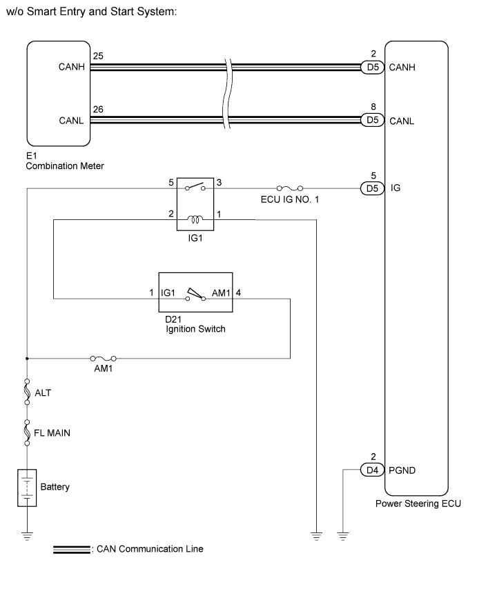
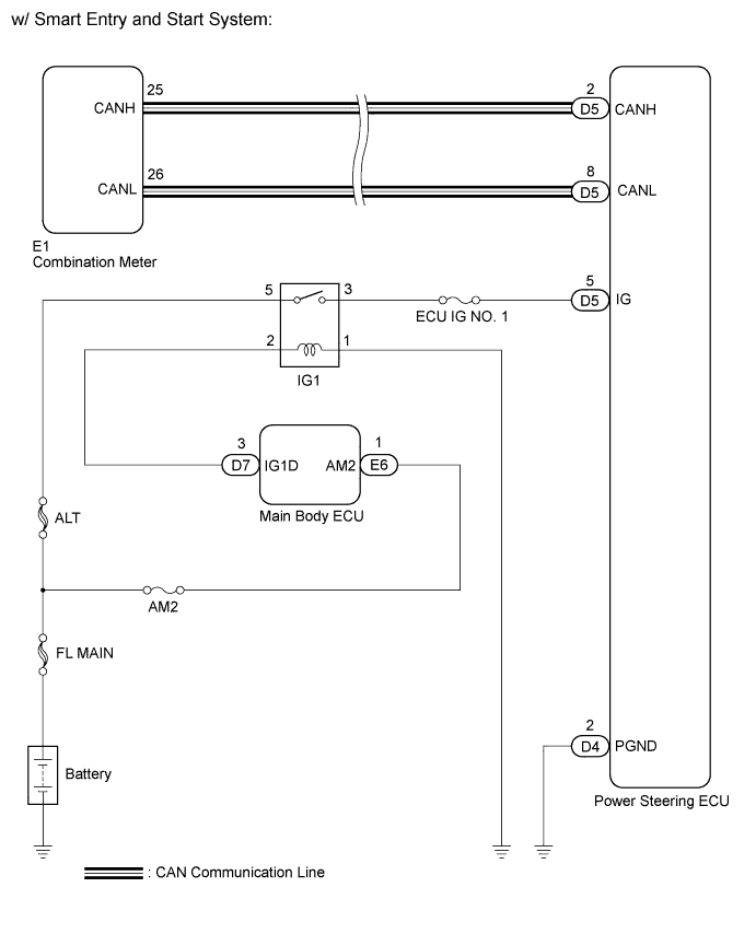
WIRING DIAGRAM
INSPECTION PROCEDURE
PROCEDURE
-
CHECK FOR DTC (CAN COMMUNICATION SYSTEM)
-
Turn the ignition switch off.
-
Connect the intelligent tester to the DLC3.
-
Turn the ignition switch on (IG).
-
Turn the intelligent tester on.
-
Using the intelligent tester, check for DTCs and confirm that there are no problems in the CAN communication system.
OK CAN DTCs are not output.
NG 
GO TO CAN COMMUNICATION SYSTEM Click here
OK 
-
-
READ VALUE USING INTELLIGENT TESTER (IG POWER SUPPLY)
-
Enter the following menus: Chassis / EMPS / Data List.
-
Select the item "IG Power Supply" in the Data List and read the value displayed on the intelligent tester.
EMPS: Tester Display Measurement Item/Range Normal Condition Diagnostic Note IG Power Supply ECU power source voltage:
Min.: 0 V
Max.: 20.1531 V
11 to 14 V Ignition switch on (IG)
NG 
INSPECT FUSE (ECU IG NO. 1) Click here
OK
-
-
PERFORM ACTIVE TEST BY INTELLIGENT TESTER
-
Enter the following menus: Body / Combination meter / Active Test.
-
According to the display on tester, perform the "Active Test".
Combination meter: Tester Display Test Part Control Range Diagnostic Note Indicat. EPS (*1) P/S Warning Light ON or OFF Confirm that the vehicle is stopped, engine idling Master Warning (*2) Master Warning Light ON or OFF Confirm that the vehicle is stopped, engine idling *1: w/o Multi-information Display
*2: w/ Multi-information Display
OK Indicator comes on.
NG
REPLACE COMBINATION METER ASSEMBLY Click here
OK 
REPLACE POWER STEERING ECU Click here
-
-
INSPECT FUSE (ECU IG NO. 1)
-
Remove the ECU IG No. 1 fuse from the instrument panel junction block.
-
Measure the resistance of the fuse.
OK Below 1 Ω
NG
REPLACE FUSE
OK
-
-
CHECK HARNESS AND CONNECTOR (POWER STEERING ECU - BATTERY AND BODY GROUND)
-
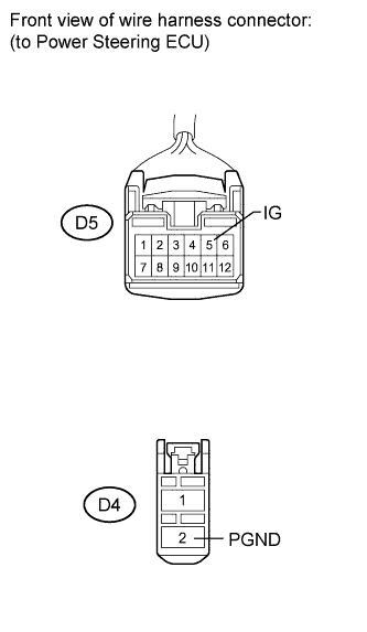
Disconnect the connectors from the power steering ECU.
-
Measure the voltage according to the value(s) in the table below.
Standard voltage Tester Connection Switch Condition Specified Condition D5-5 (IG) - Body ground Ignition switch on (IG) 11 to 14 V -
Measure the resistance according to the value(s) in the table below.
Standard resistance Tester Connection Condition Specified Condition D4-2 (PGND) - Body ground Always Below 1 Ω
NG
REPAIR OR REPLACE HARNESS OR CONNECTOR
OK
-
-
PERFORM ACTIVE TEST USING INTELLIGENT TESTER
-
Enter the following menus: Body / Combination meter / Active Test.
-
According to the display on the tester, perform the "Active Test".
Combination meter: Tester Display Test Part Control Range Diagnostic Note Indicat. EPS (*1) P/S Warning Light ON or OFF Confirm that the vehicle is stopped, engine idling Master Warning (*2) Master Warning Light ON or OFF Confirm that the vehicle is stopped, engine idling *1: w/o Multi-information Display
*2: w/ Multi-information Display
OK Indicator comes on.
NG
REPLACE COMBINATION METER ASSEMBLY Click here
OK
REPLACE POWER STEERING ECU Click here
-