| DTC Code | DTC Name |
|---|---|
| EPS Warning Light Circuit |
DESCRIPTION
If the power steering ECU detects a malfunction, the P/S warning light comes on. At this time, the power steering ECU stores a DTC in its memory.
INSPECTION PROCEDURE
PROCEDURE
- Click here
CHECK FOR DTC (CAN COMMUNICATION SYSTEM)
-
Turn the ignition switch off.
-
Connect the intelligent tester to the DLC3.
-
Turn the ignition switch on (IG).
-
Turn the intelligent tester on.
-
Using the intelligent tester, check for DTCs and confirm that there are no problems in the CAN communication system.
OK CAN DTCs are not output.
- OKClick here
- NGClick here
-
- Click here
READ VALUE USING INTELLIGENT TESTER (IG POWER SUPPLY)
-
Enter the following menus: Chassis / EMPS / Data List.
-
Select the item "IG Power Supply" in the Data List and read the value displayed on the intelligent tester.
Table 1. EMPS: Tester Display Measurement Item/Range Normal Condition Diagnostic Note IG Power Supply ECU power source voltage:
Min.: 0 V
Max.: 20.1531 V
11 to 14 V Ignition switch on (IG)
- OKClick here
- NGClick here
-
- Click here
PERFORM ACTIVE TEST BY INTELLIGENT TESTER
-
Enter the following menus: Body / Combination meter / Active Test.
-
According to the display on tester, perform the "Active Test".
Table 2. Combination meter: Tester Display Test Part Control Range Diagnostic Note Indicat. EPS (*1) P/S Warning Light ON or OFF Confirm that the vehicle is stopped, engine idling Master Warning (*2) Master Warning Light ON or OFF Confirm that the vehicle is stopped, engine idling *1: w/o Multi-information Display
*2: w/ Multi-information Display
OK Indicator comes on.
- OKClick here
- NGClick here
-
- Click here
INSPECT FUSE (ECU IG NO. 1)
-
Remove the ECU IG No. 1 fuse from the instrument panel junction block.
-
Measure the resistance of the fuse.
OK Below 1 Ω
- OKClick here
- NGClick here
-
- Click here
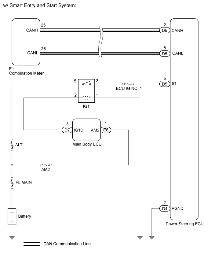
CHECK HARNESS AND CONNECTOR (POWER STEERING ECU - BATTERY AND BODY GROUND)
-
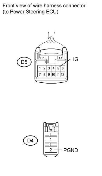
Disconnect the connectors from the power steering ECU.
-
Measure the voltage according to the value(s) in the table below.
Standard voltage Tester Connection Switch Condition Specified Condition D5-5 (IG) - Body ground Ignition switch on (IG) 11 to 14 V -
Measure the resistance according to the value(s) in the table below.
Standard resistance Tester Connection Condition Specified Condition D4-2 (PGND) - Body ground Always Below 1 Ω
- OKClick here
- NGClick here
-
- Click here
PERFORM ACTIVE TEST USING INTELLIGENT TESTER
-
Enter the following menus: Body / Combination meter / Active Test.
-
According to the display on the tester, perform the "Active Test".
Table 3. Combination meter: Tester Display Test Part Control Range Diagnostic Note Indicat. EPS (*1) P/S Warning Light ON or OFF Confirm that the vehicle is stopped, engine idling Master Warning (*2) Master Warning Light ON or OFF Confirm that the vehicle is stopped, engine idling *1: w/o Multi-information Display
*2: w/ Multi-information Display
OK Indicator comes on.
- OKClick here
- NGClick here
-
- Click here
GO TO CAN COMMUNICATION SYSTEMClick here
- Click here
REPLACE COMBINATION METER ASSEMBLYClick here
- Click here
REPLACE POWER STEERING ECUClick here
- Click here
REPLACE FUSE
- Click here
REPAIR OR REPLACE HARNESS OR CONNECTOR