POWER STEERING SYSTEM, Diagnostic DTC:C1511, C1512, C1513, C1514
| DTC Code | DTC Name |
|---|---|
| C1511 | Torque Sensor Circuit Malfunction |
| C1512 | Torque Sensor Circuit Malfunction |
| C1513 | Torque Sensor Circuit Malfunction |
| C1514 | Torque Sensor Power Supply Abnormal |
DESCRIPTION
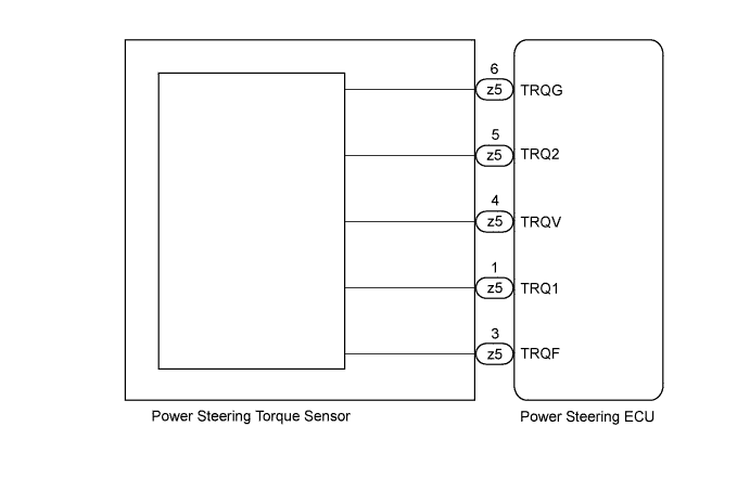
The torque sensor converts the rotation torque input from the steering wheel into electric signals and sends them to the power steering ECU.
| DTC No. | DTC Detection Condition | Trouble Area |
|---|---|---|
| C1511 | Torque sensor (TRQ1) signal error or stop |
|
| C1512 | Torque sensor (TRQ2) signal error or stop | |
| C1513 | Deviation between torque sensor TRQ1 and TRQ2 exceeds specified value | |
| C1514 | Torque sensor power source voltage error |
WIRING DIAGRAM
INSPECTION PROCEDURE
PROCEDURE
-
CHECK CONNECTOR CONNECTION CONDITION (TORQUE SENSOR - POWER STEERING ECU)
-
Check the installation condition of the torque sensor connector.
OK Torque sensor connector is securely installed to the power steering ECU. Result Result Proceed to NG A OK B
B 
CHECK TORQUE SENSOR Click here
A 
-
-
RECONFIRM DTC
-
Reinstall the torque sensor connector.
-
Check for DTCs Click here.
OK DTC is not output. Result Result Proceed to DTC is output A DTC is not output B
B 
END
A
-
-
CHECK TORQUE SENSOR
-
Turn the ignition switch on (IG).
-
Measure the voltage according to the value(s) in the table below.
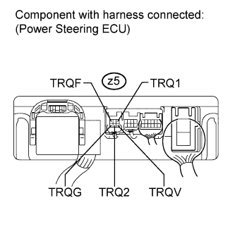
Standard voltage Tester Connection Condition Specified Condition z5-1 (TRQ1) - z5-6 (TRQG) Steering wheel not turned (without load) 2.3 to 2.7 V Steering wheel turned to right with vehicle stopped 2.5 to 4.04 V Steering wheel turned to left with vehicle stopped 0.95 to 2.5 V z5-5 (TRQ2) - z5-6 (TRQG) Steering wheel not turned (without load) 2.3 to 2.7 V Steering wheel turned to right with vehicle stopped 0.95 to 2.5 V Steering wheel turned to left with vehicle stopped 2.5 to 4.04 V z5-3 (TRQF) - z5-6 (TRQG) Always 3.35 to 3.37 V z5-4 (TRQV) - z5-6 (TRQG) Always 8.5 to 10.5 V
NG
REPLACE STEERING COLUMN ASSEMBLY Click here
OK 
REPLACE POWER STEERING ECU Click here
-