POWER STEERING SYSTEM TERMINALS OF ECU
-
CHECK POWER STEERING ECU
Tech Tips
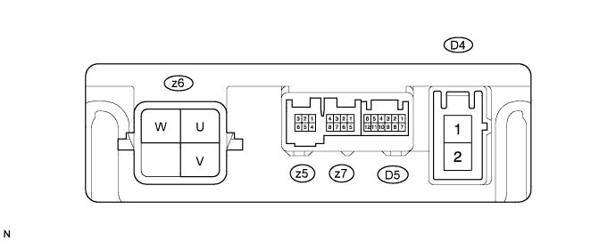
As connector "z6" uses a lock lever, each terminal cannot be checked while the connector is still connected to the power steering ECU.
Terminal No. (Symbols) Wiring Color Terminal Description z6-1 (U) W U phase motor output z6-2 (W) W-R W phase motor output z6-3 (V) B V phase motor output
-
Measure the voltage and resistance according to the value(s) in the table below.
Note
When the P/S warning light is illuminated due to a malfunction, the fail-safe function may cause the voltage of the power steering ECU's terminal to become 0 V.
Terminal No. (Symbols) Wiring Color Terminal Description Condition Specified Condition D4-1 (PIG) - D4-2 (PGND) B - W Power source Always 11 to 14 V D5-5 (IG) - D4-2 (PGND) G - W IG power source Ignition switch on (IG) 11 to 14 V z5-6 (TRQ1) - z5-1 (TRQG) G - B Torque sensor signal Ignition switch on (IG), steering wheel not turned (without load) 2.3 to 2.7 V Ignition switch on (IG), steering wheel turned to right with vehicle stopped 2.5 to 4.04 V Ignition switch on (IG), steering wheel turned to left with vehicle stopped 0.95 to 2.5 V z5-2 (TRQ2) - z5-1 (TRQG) Y - B Torque sensor signal Ignition switch on (IG), steering wheel not turned (without load) 2.3 to 2.7 V Ignition switch on (IG), steering wheel turned to right with vehicle stopped 0.95 to 2.5 V Ignition switch on (IG), steering wheel turned to left with vehicle stopped 2.5 to 4.04 V z5-4 (TRQF) - z5-1 (TRQG) W - B Torque sensor reference voltage Ignition switch on (IG) 3.35 to 3.37 V z5-3 (TRQV) - z5-1 (TRQG) R - B Torque sensor voltage source Ignition switch on (IG) 8.5 to 10.5 V z5-1 (TRQG) - Body ground B - Body ground Torque sensor ground Always Below 1 Ω D4-2 (PGND) - Body ground W - Body ground Power ground Always Below 1 Ω z7-1 (C1) - D4-2 (PGND) R - W Resolver signal Ignition switch on (IG), steering wheel is turned 0.68 to 4.42 V z7-5 (C2) - D4-2 (PGND) L - W Resolver signal Ignition switch on (IG), steering wheel is turned 0.68 to 4.42 V z7-2 (S1) - D4-2 (PGND) B - W Resolver signal Ignition switch on (IG), steering wheel is turned 0.68 to 4.42 V z7-6 (S2) - D4-2 (PGND) Y - W Resolver signal Ignition switch on (IG), steering wheel is turned 0.68 to 4.42 V z7-4 (R1) - D4-2 (PGND) W - W Resolver excitation signal Ignition switch on (IG), steering wheel is turned 2.9 to 5.1 V z7-8 (R2) - D4-2 (PGND) G - W Resolver excitation signal Ignition switch on (IG), steering wheel is turned 2.9 to 5.1 V D5-2 (CANH) - D5-8 (CANL) BR - W CAN communication line Ignition switch off 54 to 67 Ω If the result is not as specified, the ECU may have a malfunction.
-