STEERING COLUMN ASSEMBLY REMOVAL
CAUTION:
Some of these service operations affect the SRS airbag system. Read the precautionary notices concerning the SRS airbag system before servicing the steering column Click here.
-
PRECAUTION
-
POSITION FRONT WHEELS STRAIGHT AHEAD
-
DISCONNECT CABLE FROM NEGATIVE BATTERY TERMINAL
CAUTION:
Wait at least 90 seconds after disconnecting the cable from the negative (-) battery terminal to prevent airbag and seat belt pretensioner activation.
Note
When disconnecting the cable, some systems need to be initialized after the cable is reconnected Click here.
-
REMOVE FRONT WHEEL LH
-
REMOVE STEERING PAD
-
REMOVE STEERING WHEEL ASSEMBLY
-
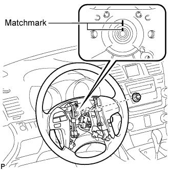
Remove the steering wheel assembly set nut.
-
Put matchmarks on the steering wheel assembly and the steering main shaft.
-
Disconnect the connectors from the spiral cable.
-
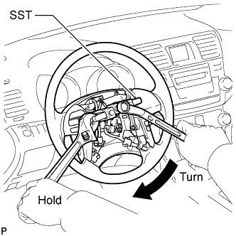
Using SST, remove the steering wheel assembly.
- SST
- 09950-50013 ( 09951-05010, 09952-05010, 09953-05020, 09954-05021 )
Note
Apply a small amount of grease to the threads and tip of SST (09953-05020) before use.
-
-
REMOVE DRIVER SIDE KNEE AIRBAG ASSEMBLY
-
REMOVE BRAKE PEDAL RETURN SPRING
-
Remove the brake pedal return spring from the push rod pin and instrument panel reinforcement.
-
-
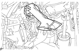
REMOVE STOP LIGHT SWITCH ASSEMBLY
-
Disconnect the connector.
-
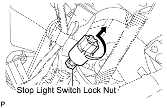
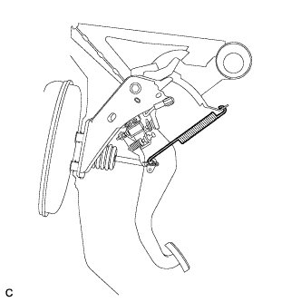
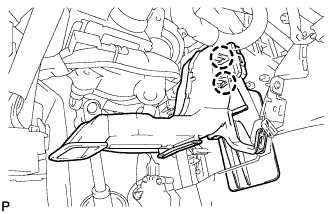
Loosen the stop light switch lock nut.
-
Remove the stop light switch assembly as shown in the illustration.
-
-
SEPARATE BRAKE MASTER CYLINDER PUSH ROD CLEVIS
-
Remove the clip and push rod pin, and separate the brake master cylinder push rod clevis from the brake pedal sub-assembly.
-
-
REMOVE BRAKE PEDAL SUPPORT SUB-ASSEMBLY (for LHD)
-
Disconnect the brake pedal load sensing switch connector and disengage the clamp.
-
Remove the 2 bolts and separate the brake pedal support sub-assembly from the instrument panel reinforcement.
-
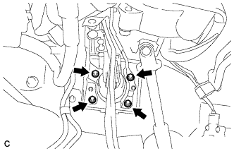
Remove the 4 nuts and brake pedal support sub-assembly from the body.
-
-
REMOVE BRAKE PEDAL SUPPORT SUB-ASSEMBLY (for RHD)
-
Disconnect the brake pedal load sensing switch connector and disengage the clamp.
-
Remove the 2 bolts and separate the brake pedal support sub-assembly from the instrument panel reinforcement.
-
Remove the 4 nuts and brake pedal support sub-assembly from the body.
-
-
REMOVE STEERING COLUMN COVER
-
Remove the 2 screws.
-
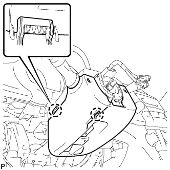
Disengage the 2 claws to remove the lower steering column cover.
-
Disengage the claw to remove the upper steering column cover.
-
-
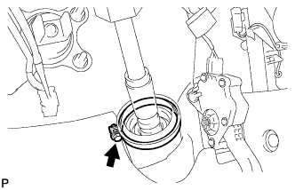
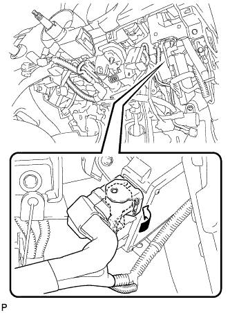
REMOVE TURN SIGNAL SWITCH ASSEMBLY WITH SPIRAL CABLE SUB-ASSEMBLY
-
Disconnect the connectors from the turn signal switch assembly with spiral cable sub-assembly.
-
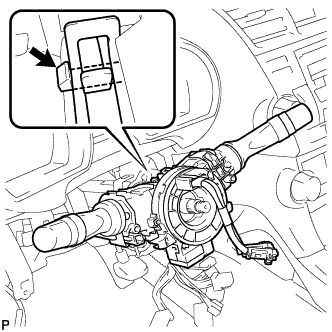
Using pliers, grip the claws of the clip and remove the turn signal switch assembly with spiral cable sub-assembly.
-
-
REMOVE NO. 1 AIR DUCT SUB-ASSEMBLY (for LHD)
-
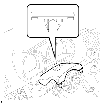
Disengage the 2 claws and remove the No. 1 air duct sub-assembly.
-
-
REMOVE NO. 1 AIR DUCT SUB-ASSEMBLY (for RHD)
-
Disengage the 2 claws and remove the No. 1 air duct sub-assembly.
-
-
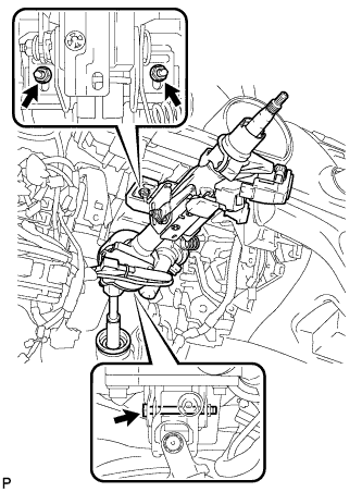
SEPARATE STEERING INTERMEDIATE SHAFT SUB-ASSEMBLY
-
Loosen the bolt.
-
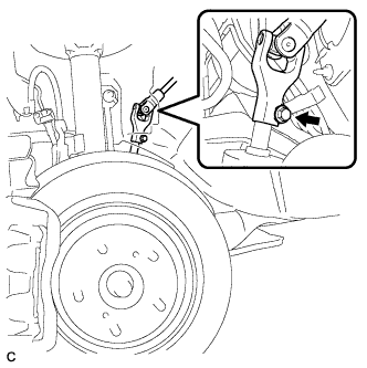
Remove the bolt and slide the steering intermediate shaft sub-assembly.
Note
Do not separate the steering intermediate shaft sub-assembly from the power steering link assembly.
-
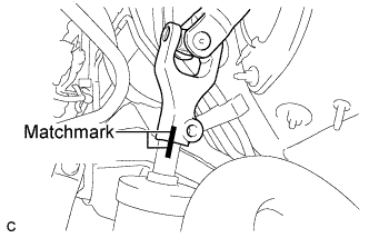
Put matchmarks on the steering intermediate shaft sub-assembly and the power steering link assembly.
-
Separate the steering intermediate shaft sub-assembly from the power steering link assembly.
-
-
REMOVE STEERING COLUMN ASSEMBLY (for LHD)
-
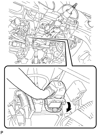
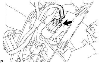
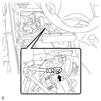
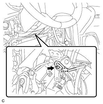
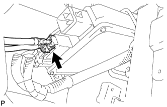
Disconnect the connector from the power steering ECU assembly.
Tech Tips
As shown in the illustration, turn the lock lever to disconnect the connector.
-
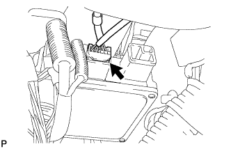
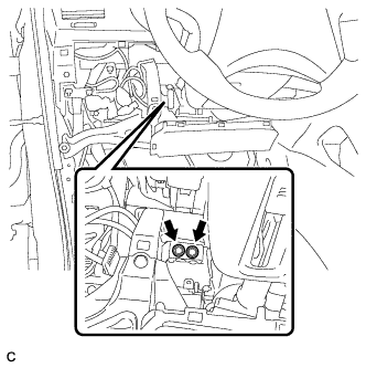
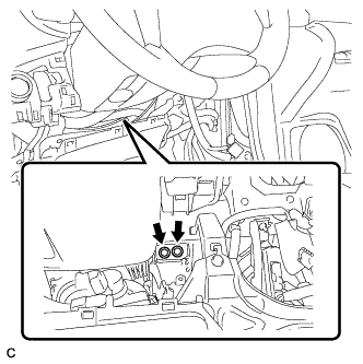
Disconnect the connector from the power steering ECU assembly.
-
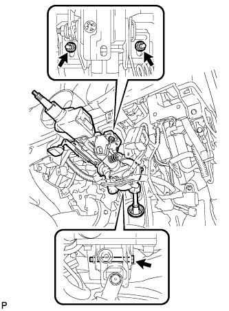
Disconnect the connectors and disengage the wire harness clamps from the steering column assembly.
-
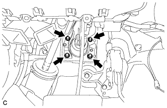
Remove the bolt, 2 nuts, and the steering column assembly.
-
-
REMOVE STEERING COLUMN ASSEMBLY (for RHD)
-
Disconnect the connector from the power steering ECU assembly.
Tech Tips
As shown in the illustration, turn the lock lever to disconnect the connector.
-
Disconnect the connector from the power steering ECU assembly.
-
Disconnect the connectors and disengage the wire harness clamps from the steering column assembly.
-
Remove the bolt, 2 nuts, and the steering column assembly.
-
-
REMOVE STEERING INTERMEDIATE SHAFT SUB-ASSEMBLY
-
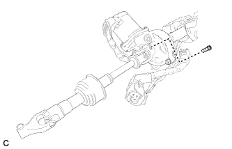
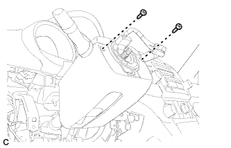
Remove the bolt.
-
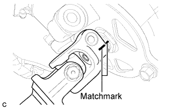
Put matchmarks on the steering intermediate shaft assembly and the steering column assembly.
-
Remove the steering intermediate shaft assembly from the steering column assembly.
-