STEERING LOCK SYSTEM, Diagnostic DTC:B2782
| DTC Code | DTC Name |
|---|---|
| B2782 | Power Source Control ECU Malfunction |
DESCRIPTION
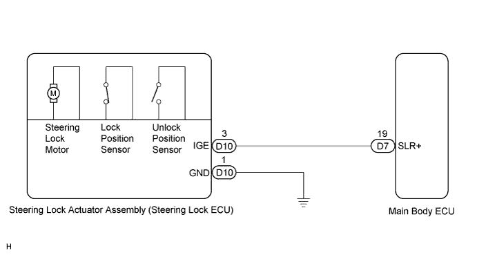
The steering lock ECU activates the steering lock motor by the power from the main body ECU (*) through the IGE circuit. This prevents the steering from being locked while the vehicle is moving.
The diagnosis information of the steering lock ECU is transmitted to the tester via the certification ECU (smart key ECU assembly) as the steering lock ECU is not connected to the CAN communication system.
Tech Tips
*: The power source control ECU is not a physical part. This code refers to the power source control function performed by the main body ECU.
| DTC No. | DTC Detecting Condition | Trouble Area |
|---|---|---|
| B2782 | Steering lock motor drive control circuit is defective. |
|
WIRING DIAGRAM
INSPECTION PROCEDURE
When the engine switch is off, the main body ECU may occasionally go into a non-active state called sleep mode. Therefore, before proceeding with the inspection, it is necessary to perform the following step to wake up the ECU:
Before starting the inspection, with the engine switch off, open the driver's door. Then (with the engine switch still off) open and close any door several times in 1.5-second intervals.
Note
If the steering lock actuator assembly (steering lock ECU) is replaced, with the engine switch off and the shift lever in the N position, open and close the driver's door to record the current lock position into the steering lock ECU. If this is not performed, the engine may not start.
PROCEDURE
-
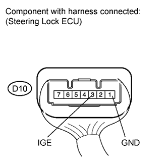
INSPECT STEERING LOCK ACTUATOR ASSEMBLY (STEERING LOCK ECU)
-
Measure the voltage according to the value(s) in the table below.
Standard voltage Tester Connection Condition Specified Condition D10-3 (IGE) - D10-1 (GND) The specified condition should be checked after performing the following:
-
Turn the engine switch off
-
Turn the engine switch on (ACC or IG)
-
Motor activated: Below 1 V
-
Motor not activated: 11 to 14 V
D10-3 (IGE) - D10-1 (GND) The specified condition should be checked after performing the following:
-
Move the shift lever to the P position
-
Turn the engine switch off
-
Open the driver's door
-
Motor activated: Below 1 V
-
Motor not activated: 11 to 14 V
Tech Tips
The steering lock ECU and steering lock actuator assembly are supplied as a unit.
-
NG 
CHECK HARNESS AND CONNECTOR (STEERING LOCK ACTUATOR ASSEMBLY - BODY GROUND) Click here
OK 
REPLACE STEERING LOCK ACTUATOR ASSEMBLY (STEERING LOCK ECU) Click here
-
-
CHECK HARNESS AND CONNECTOR (STEERING LOCK ACTUATOR ASSEMBLY - BODY GROUND)
-
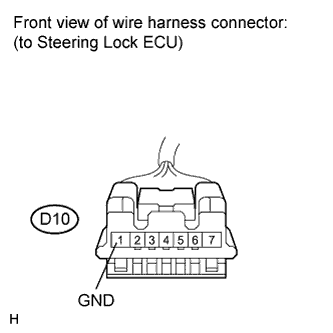
Disconnect the D10 connector from the steering lock actuator assembly.
-
Measure the resistance according to the value(s) in the table below.
Standard resistance Tester Connection Switch Condition Specified Condition D10-1 (GND) - Body ground Always Below 1 Ω
NG 
REPAIR OR REPLACE HARNESS OR CONNECTOR
OK 
-
-
CHECK HARNESS AND CONNECTOR (STEERING LOCK ACTUATOR ASSEMBLY - MAIN BODY ECU)
-
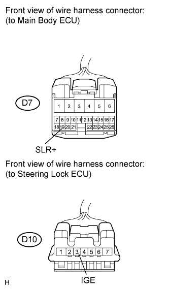
Disconnect the D7 connector from the main body ECU.
-
Measure the resistance according to the value(s) in the table below.
Standard resistance Tester Connection Switch Condition Specified Condition D10-3 (IGE) - D7-19 (SLR+) Always Below 1 Ω D10-3 (IGE) - Body ground Always 10 kΩ or higher
NG
REPAIR OR REPLACE HARNESS OR CONNECTOR
OK
REPLACE MAIN BODY ECU
-