STEERING LOCK SYSTEM TERMINALS OF ECU
-
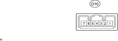
STEERING LOCK ACTUATOR ASSEMBLY (STEERING LOCK ECU)
Terminal No. (Symbols) Wiring Color Terminal Description Condition Specified Condition D10-1 (GND) - Body ground W-B - Body ground Ground Always Below 1 V D10-2 (SGND) - Body ground W - Body ground Signal ground Always Below 1 V D10-3 (IGE) - D10-1 (GND) Y - W-B Power source for driving motor Motor is in operation Below 1 V Motor is not in operation 11 to 14 V D10-4 (SLP1) - D10-2 (SGND) O - W Unlock position sensor output signal Steering is locked 11 to 14 V Steering lock is released Below 1 V D10-5 (LIN) - D10-2 (SGND) GR - W LIN communication bus Engine switch on (IG) Pulse generation D10-6 (IG2) - D10-1 (GND) V - W-B IG signal input Engine switch on (IG) 11 to 14 V D10-7 (B) - D10-1 (GND) G - W-B Power source Always 11 to 14 V