POWER STEERING SYSTEM SYSTEM DESCRIPTION
-
GENERAL
-
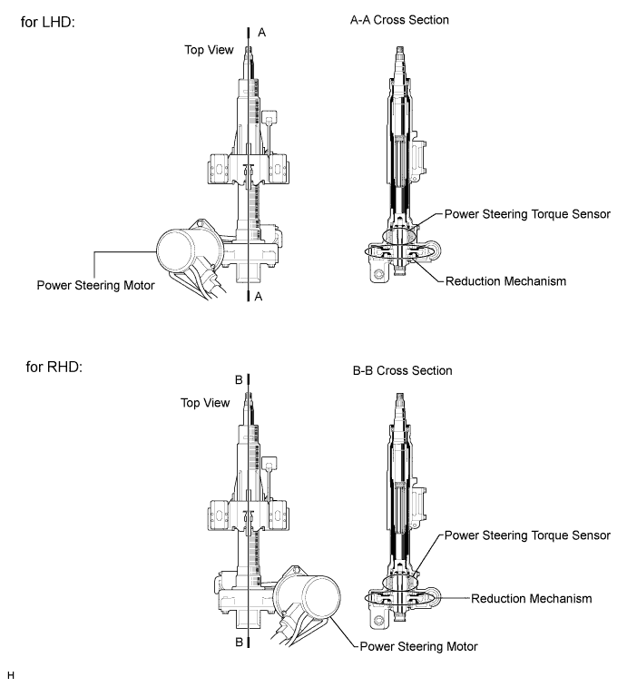
The power steering system uses a power steering motor, a power steering torque sensor and a reduction mechanism that are built into the steering column assembly to generate assist torque in order to assist the driver's steering effort.
-
This system activates the power steering motor only when the driver turns the steering wheel. As a result, no energy is consumed when the vehicle is going straight, enhancing fuel economy.
-
-
-
FUNCTION OF MAIN COMPONENTS
-
The power steering system components function has the following:
Component Function Steering Column Assembly Power Steering Torque Sensor Detects the twist of the torsion bar. Based on the torque that is applied to the torsion bar, the sensor creates an electrical signal, and outputs this signal to the power steering ECU. Power Steering Motor Generates power assist in accordance with a signal received from the power steering ECU. Motor Rotation Angle Sensor (built into Power Steering Motor) Outputs the rotation angle of the power steering motor to the power steering ECU. Reduction Mechanism Reduces the speed of the power steering motor through the use of a worm gear and a wheel gear and transmits it to the column shaft. Power Steering ECU Actuates the power steering motor mounted on the steering column assembly to provide power assist, based on the signals received from various sensors and vehicle speed. P/S Warning Light Lights up to alert the driver when the power steering ECU detects a malfunction in the power steering system. Master Warning Light (*) Lights up to alert the driver when the power steering ECU detects a malfunction in the power steering system. Multi-information Display (*) Shows a warning message to alert the driver when the power steering ECU detects a malfunction in the power steering system. ECM Outputs the engine speed signal to the power steering ECU. Skid Control ECU with Actuator Outputs the vehicle speed signal to the power steering ECU. *: w/ Multi-information display
-
Steering Column Assembly
-
The steering column assembly includes a power steering torque sensor, power steering motor, and reduction mechanism.
-
-
Power Steering Torque Sensor
-
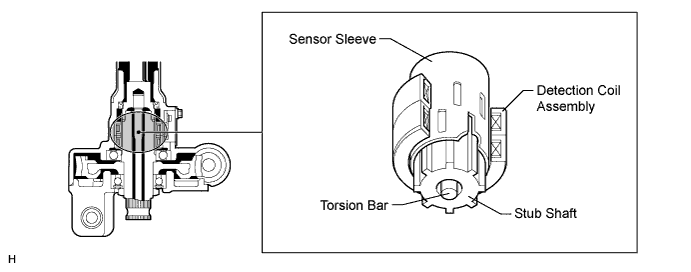
Power steering torque sensor consists of the sensor sleeve, stub shaft and detection coil. This sensor outputs 2 types of signals to the power steering ECU.
-
The sensor sleeve is mounted on the input shaft, and the stub shaft is mounted on the output shaft. The input shaft and the output shaft are joined by the torsion bar.
-
The detection coil assembly is placed on the outside of the sensor sleeve to complete an excitation circuit without making a contact.
-
-
Steering Torque and Steering Direction Detection
-
When the steering wheel is not turned:
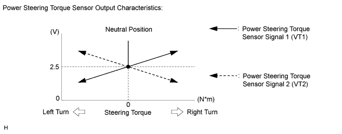
When the driver does not turn the steering wheel, the power steering torque sensor outputs a specified voltage (2.5 V) to the power steering ECU. As long as the specified voltage is output, the power steering ECU determines that the steering wheel is in the neutral position.
-
-
When the steering wheel is turned:
When the driver turns the steering wheel to the right or left, twist that is created in the torsion bar creates a relative displacement between the sensor sleeve and the stub shaft. At this time, the voltage output from the torque sensor to the power steering ECU changes. Based on the changes, the power steering ECU determines the steering torque and steering direction input by the driver.
-
-
Power Steering Motor
-
A low inertia, low noise, and high power output power steering motor is used.
-
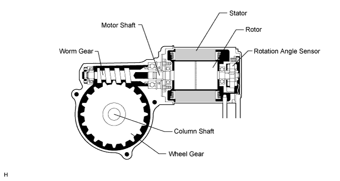
The motor consists of the rotor, stator, motor shaft and rotation angle sensor.
-
The torque that is generated by the motor is transmitted via the joint to the worm gear. Then this torque is transmitted via the wheel gear to the column shaft.
-
The rotation angle sensor consists of the resolver sensor, which excels in reliability and durability. The rotation angle sensor detects the rotation angle of the motor and outputs it to the power steering ECU. As a result, it ensures efficient EPS control.
-
-
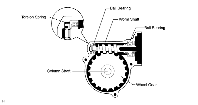
Reduction Mechanism
-
This mechanism reduces the speed of the power steering motor via the worm gear and the wheel gear, and transmits it to the column shaft.
-
The wheel gear is made of a high strength, low friction, and low wear plastic material, to realize low noise and a lightweight construction.
-
A worm gear supported by ball bearings is used. Also, a torsion spring is provided to ensure the optimal meshing of the gears at all times.
-
-
-
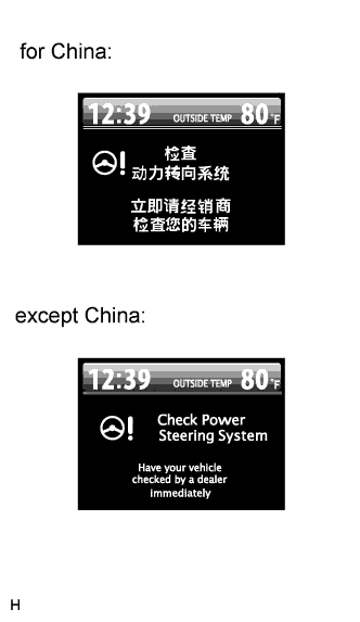
Multi-information Display
-
The multi-information display shows a warning message to inform the driver that there is a malfunction in the power steering system.
-
-
-
SYSTEM CONTROL
-
General
-
The power steering system has the following controls:
Control Outline Basic Control Calculates the assist current from the steering torque value and the vehicle speed, and actuates the power steering motor. Inertia Compensation Control Ensures the starting movement of the power steering motor when the driver starts to turn the steering wheel. Recovery Control During the short interval between the time the driver fully turns the steering wheel and the wheels try to recover, this control assists the recovery force. Damper Control Regulates the amount of assist when the driver turns the steering wheel while driving at high speeds, thus damping the changes in the yaw rate of the vehicle body. System Overheat Protection Control Estimates the power steering motor temperature based on the amperage and the current duration. If the temperature exceeds the standard, it limits the amperage to prevent the power steering motor from overheating. Diagnosis If the power steering ECU detects a malfunction in the power steering system, the power steering ECU lights up the P/S warning light to warn the driver and stores the DTCs (Diagnostic Trouble Codes) in memory. Fail-safe If the power steering ECU detects a malfunction in the power steering system, the power steering ECU changes the control mode to a fail-safe mode, thus enabling the vehicle to be driven.
-
-
Basic Control
-
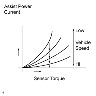
The power steering ECU receives the vehicle speed signal and signals from various sensors. Based on these signals, the power steering ECU judges the current vehicle condition, and determines the assist current to be applied to the power steering motor.
-
The diagram below describes the relationship between the steering torque and the assist power current.
-
-
-
Diagnosis
-
If the power steering ECU detects a malfunction in the power steering system, the power steering ECU lights up the P/S warning light in order to alert the driver. At the same time, DTCs (Diagnostic Trouble Codes) are stored in memory.
-
These DTCs can be read by connecting an intelligent tester to the DLC3 Click here.
-
-
-
Fail-safe
-
Fail-safe operation modes are as follows:
Item Control Power Steering Torque Sensor Malfunction Disables the assist. Power Steering Motor Overcurrent Disables the assist. Power Steering Motor Short (Including drive system malfunction) Disables the assist. Power Steering Motor Rotation Angle Sensor Malfunction Disables the assist. Power Steering ECU Internal Temperature Sensor Malfunction Limits the assist force. Power Steering ECU System Malfunction Disables the assist. Vehicle Speed and Engine Speed Signals Malfunction Limits the assist force. Power Supply Voltage Malfunction Pauses the assist.
(Provides normal assist after voltage recovers.)
-
-