PARKING BRAKE CABLE INSTALLATION
Note
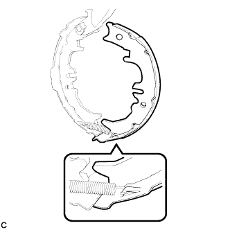
Before installation, apply high temperature grease to the parts indicated by arrows Click here.
-
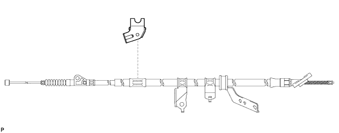
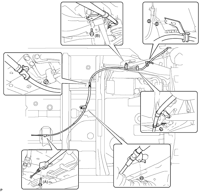
INSTALL CABLE SUPPORT BRACKET
-
Install the cable support bracket to the No. 3 parking brake cable assembly.
-
-
INSTALL NO. 3 PARKING BRAKE CABLE ASSEMBLY
-
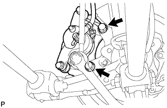
Install the No. 3 parking brake cable assembly with the 2 bolts and 4 nuts.
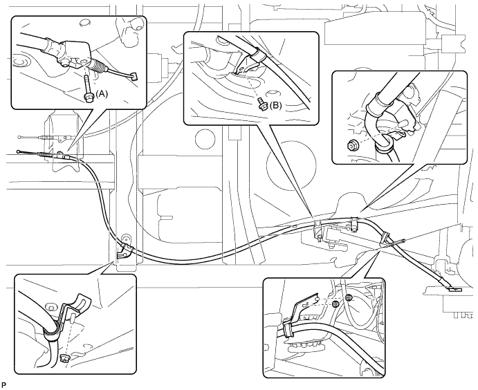
- Torque:
- Bolt (A)
- 8.5 N*m { 87 kgf*cm, 75 in.*lbf }
- Bolt (B)
- 6.0 N*m { 61 kgf*cm, 53 in.*lbf }
- Nut
- 6.0 N*m { 61 kgf*cm, 53 in.*lbf }
-

Install the No. 3 parking brake cable assembly to the backing plate with the 2 bolts.
- Torque:
- 8.0 N*m { 82 kgf*cm, 71 in.*lbf }
-
-
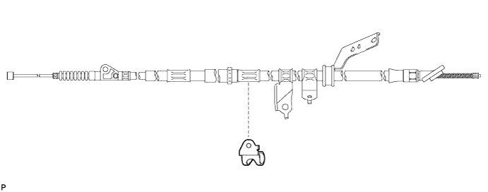
INSTALL NO. 1 PARKING BRAKE CABLE SUPPORT BRACKET
-
Install the No. 1 parking brake cable support bracket to the No. 2 parking brake cable assembly.
-
-
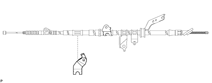
INSTALL PARKING BRAKE CABLE SUPPORT BRACKET
-
Install the parking brake cable support bracket to the No. 2 parking brake cable assembly.
-
-
INSTALL NO. 2 PARKING BRAKE CABLE ASSEMBLY
-
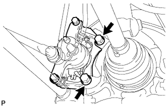
Install the No. 2 parking brake cable assembly with the 2 bolts and 5 nuts.
- Torque:
- Bolt (A)
- 8.5 N*m { 87 kgf*cm, 75 in.*lbf }
- Bolt (B)
- 6.0 N*m { 61 kgf*cm, 53 in.*lbf }
- Nut
- 6.0 N*m { 61 kgf*cm, 53 in.*lbf }
-
Install the No. 2 parking brake cable assembly to the backing plate with the 2 bolts.
- Torque:
- 8.0 N*m { 82 kgf*cm, 71 in.*lbf }
-
-
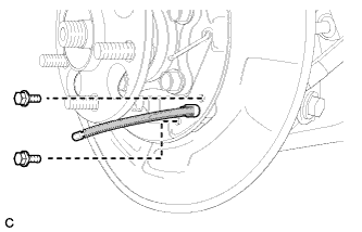
APPLY HIGH TEMPERATURE GREASE
-
Apply high temperature grease to the backing plate which makes contact with the shoe.
-
-
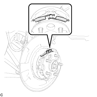
INSTALL NO. 2 PARKING BRAKE SHOE ASSEMBLY WITH PARKING BRAKE SHOE LEVER
-
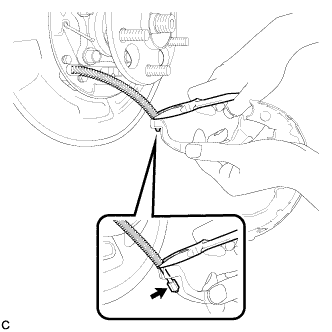
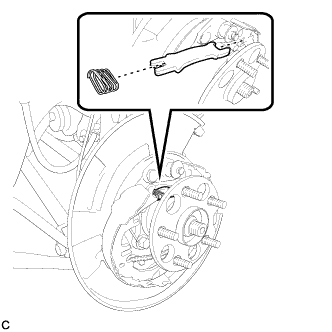
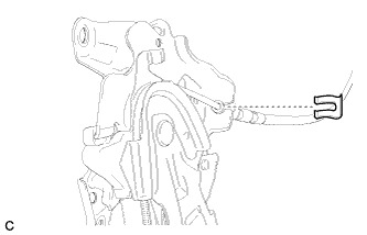
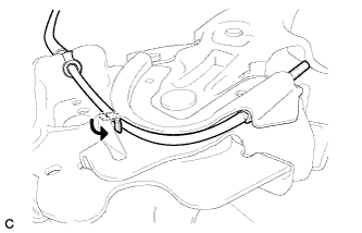
Using needle-nose pliers, connect the No. 3 parking brake cable assembly to the parking brake shoe lever as shown in the illustration.
-
-
INSTALL NO. 2 PARKING BRAKE SHOE RETURN TENSION SPRING
-
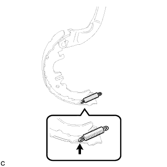
Install the No. 2 parking brake shoe return tension spring to the No. 2 parking brake shoe assembly.
-
-
INSTALL NO. 1 PARKING BRAKE SHOE ASSEMBLY
-
Connect the No. 2 parking brake shoe return tension spring to install the No. 1 parking brake shoe assembly.
-
-
INSTALL PARKING BRAKE SHOE ADJUSTING SCREW SET
-
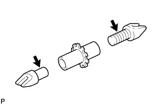
Apply high temperature grease to the parking brake shoe adjusting screw set as shown in the illustration.
-
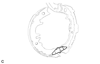
Install the parking brake shoe adjusting screw set.
-
-
INSTALL NO. 2 PARKING BRAKE SHOE ASSEMBLY
-

Install the No. 2 parking brake shoe assembly to the backing plate with the No. 1 parking brake shoe hold down spring cup, parking brake shoe hold down spring, and No. 2 parking brake shoe hold down spring cup.
-
-
INSTALL PARKING BRAKE SHOE STRUT
-
Install the parking brake shoe strut and the parking brake shoe strut compression spring.
-
-
INSTALL NO. 1 PARKING BRAKE SHOE ASSEMBLY
-
Install the No. 1 parking brake shoe assembly to the backing plate with the No. 1 parking brake shoe hold down spring cup, parking brake shoe hold down spring, and No. 2 parking brake shoe hold down spring cup.
-
-
INSTALL NO. 1 PARKING BRAKE SHOE RETURN TENSION SPRING
-
Install the 2 No. 1 parking brake shoe return tension springs.
Tech Tips
First install the front side spring and then the rear side spring.
-
-
CHECK PARKING BRAKE INSTALLATION
-
Check that each part is installed properly.
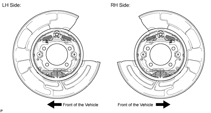
Note
There should be no oil or grease on the friction surface of the shoe lining and disc.
-
-
INSTALL REAR DISC
-
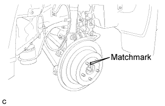
Align matchmarks and install the rear disc.
Note
When replacing the rear disc with a new one, select the installation position where the rear disc has minimal runout.
-
-
INSTALL REAR DISC BRAKE CALIPER ASSEMBLY (for 2WD)
-
Install the rear disc brake caliper assembly with the 2 bolts.
- Torque:
- 78 N*m { 795 kgf*cm, 57 ft.*lbf }
-
-
INSTALL REAR DISC BRAKE CALIPER ASSEMBLY (for 4WD)
-
Install the rear disc brake caliper assembly with the 2 bolts.
- Torque:
- 78 N*m { 795 kgf*cm, 57 ft.*lbf }
-
-
INSTALL NO. 1 PARKING BRAKE CABLE ASSEMBLY
-
Pass the No. 1 parking brake cable assembly through the parking brake pedal.
-
Install the clip to the No. 1 parking brake cable assembly.
-
Temporarily install the adjusting nut.
-
Bend the parking brake pedal claw.
-
-
INSTALL PARKING BRAKE CONTROL PEDAL ASSEMBLY
Tech Tips
Refer to the instructions for INSTALLATION of the parking brake pedal Click here.
-
ADJUST PARKING BRAKE SHOE CLEARANCE AND PARKING BRAKE PEDAL TRAVEL (for LHD)
-
Remove the driver side knee airbag assembly Click here.
-
Completely release the parking brake pedal.
-
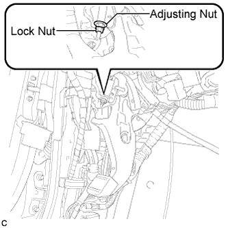
Loosen the lock nut and the adjusting nut to completely release the parking brake cable.
-
Remove the rear wheel.
-
Temporarily install the hub nuts.
-
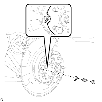
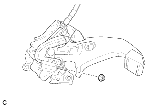
Remove the shoe adjusting hole plug.
-
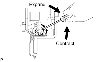
Turn the shoe adjuster and expand the shoe until the disc locks.
-
Turn and contract the shoe adjuster until the disc can rotate smoothly.
Standard Return 8 notches. -
Check that there is no brake drag against the shoe.
-
Install the shoe adjusting hole plug.
-
Turn the adjusting nut until the parking brake pedal travel is corrected to be within the specified range.
Parking brake pedal travel 8 to 10 notches at 300 N (31 kgf, 67 lbf) -
Using a wrench or an equivalent tool, hold the adjusting nut and tighten the lock nut.
- Torque:
- 7.0 N*m { 71 kgf*cm, 62 in.*lbf }
-
Operate the parking brake pedal 3 to 4 times, and check the parking brake pedal travel.
-
Check that there is no brake drag against the shoe.
-
Remove the hub nuts.
-
Install the rear wheel.
- Torque:
- 103 N*m { 1050 kgf*cm, 76 ft.*lbf }
-
Install the driver side knee airbag assembly Click here.
-
-
ADJUST PARKING BRAKE SHOE CLEARANCE AND PARKING BRAKE PEDAL TRAVEL (for RHD)
-
Remove the driver side knee airbag assembly Click here.
-
Completely release the parking brake pedal.
-
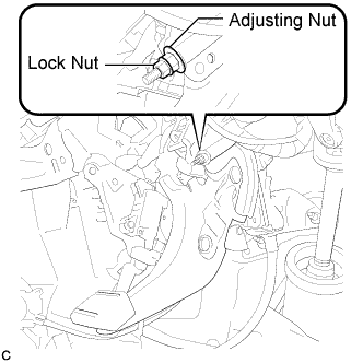
Loosen the lock nut and adjusting nut to completely release the parking brake cable.
-
Remove the rear wheel.
-
Temporarily install the hub nuts.
-
Remove the shoe adjusting hole plug.
-
Turn the shoe adjuster and expand the shoe until the disc locks.
-
Turn and contract the shoe adjuster until the disc can rotate smoothly.
Standard Return 8 notches. -
Check that there is no brake drag against the shoe.
-
Install the shoe adjusting hole plug.
-
Turn the adjusting nut until the parking brake pedal travel is corrected to be within the specified range.
Parking brake pedal travel 8 to 10 notches at 300 N (31 kgf, 67 lbf) -
Using a wrench or an equivalent tool, hold the adjusting nut and tighten the lock nut.
- Torque:
- 7.0 N*m { 71 kgf*cm, 62 in.*lbf }
-
Operate the parking brake pedal 3 to 4 times, and check the parking brake pedal travel.
-
Check that there is no brake drag against the shoe.
-
Remove the hub nuts.
-
Install the rear wheel.
- Torque:
- 103 N*m { 1050 kgf*cm, 76 ft.*lbf }
-
Install the driver side knee airbag assembly Click here.
-
-
INSPECT BRAKE WARNING LIGHT
-
When operating the parking brake pedal, check that the brake warning light illuminates.
Standard The brake warning light always illuminates at the first click.
-
-
INSTALL REAR WHEEL
- Torque:
- 103 N*m { 1050 kgf*cm, 76 ft.*lbf }