- Click here
INSTALL PARKING BRAKE CONTROL PEDAL ASSEMBLY (for LHD)
-
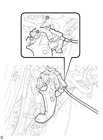
Install the parking brake control pedal assembly with the 3 nuts.
21 N*m 214 kgf*cm 15 ft.*lbf -
Connect the parking brake switch connector.
-
Insert the No. 1 parking brake cable assembly toward the outside of the cabin.
-
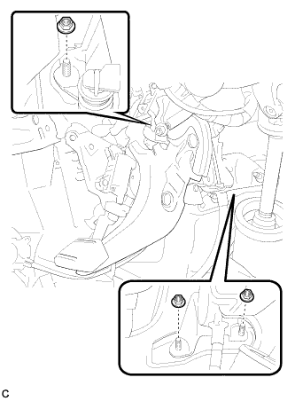
Install the No. 1 parking brake cable assembly with the 2 bolts and 2 nuts.
Bolt 8.5 N*m 87 kgf*cm 75 in.*lbf Nut 6.0 N*m 61 kgf*cm 53 in.*lbf -
Install the clamp.
-
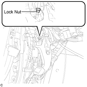
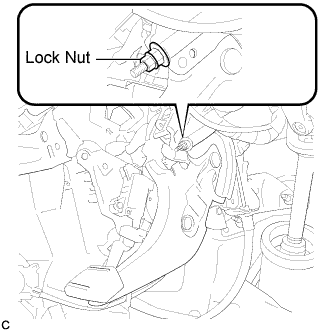
Temporarily install the lock nut.
Tip:After adjusting parking brake pedal travel, tighten the lock nut.
-
- Click here
INSTALL PARKING BRAKE CONTROL PEDAL ASSEMBLY (for RHD)
-
Install the parking brake control pedal assembly with the 3 nuts.
21 N*m 214 kgf*cm 15 ft.*lbf -
Connect the parking brake switch connector.
-
Insert the No. 1 parking brake cable assembly toward the outside of the cabin.
-
Install the No. 1 parking brake cable assembly to the body with the 2 bolts and 3 nuts.
Bolt 8.5 N*m 87 kgf*cm 75 in.*lbf Nut 6.0 N*m 61 kgf*cm 53 in.*lbf -
Install the clamp.
-
Temporarily install the lock nut.
Tip:After adjusting parking brake pedal travel, tighten the lock nut.
-
- Click here
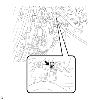
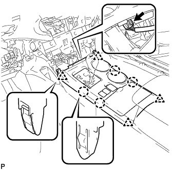
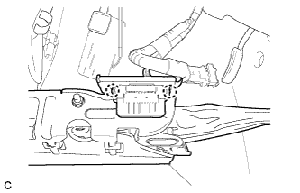
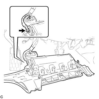
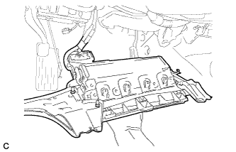
INSTALL INSTRUMENT PANEL JUNCTION BLOCK ASSEMBLY (for LHD)
-
Connect the connectors to the back of the instrument panel junction block assembly.
-
Engage the wire harness clamp onto the instrument panel junction block assembly.
-
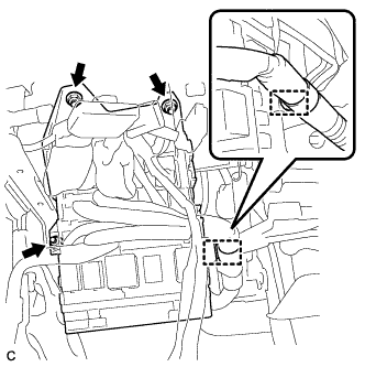
Install the instrument panel junction block assembly with the 3 nuts.
8.4 N*m 86 kgf*cm 74 in.*lbf -
Connect the connectors to the instrument panel junction block assembly.
-
Engage the wire harness clamp onto the instrument panel junction block assembly.
-
- Click here
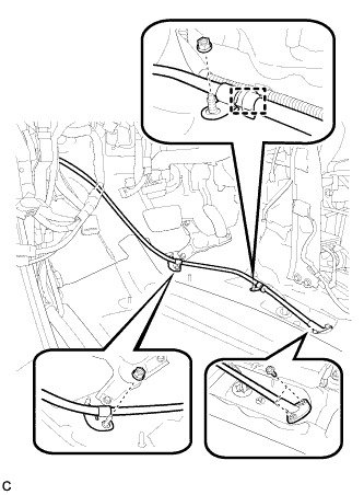
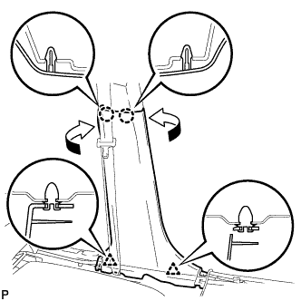
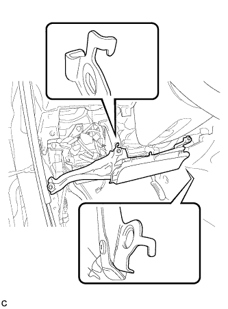
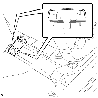
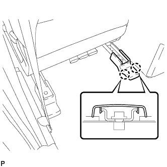
INSTALL PARKING BRAKE EQUALIZER
-
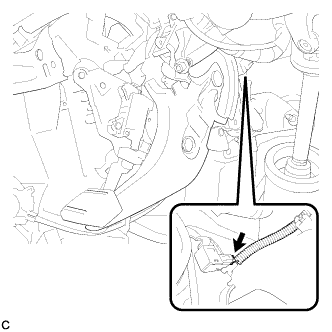
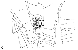
Install the parking brake equalizer to the No. 1 parking brake cable assembly as shown in the illustration.
-
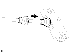
Slide the rubber boot back as shown in the illustration.
-
- Click here
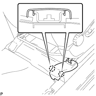
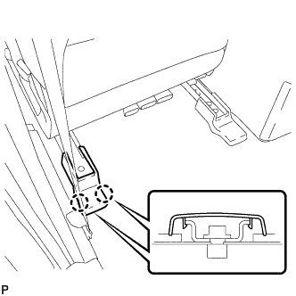
CONNECT NO. 3 PARKING BRAKE CABLE ASSEMBLY
-
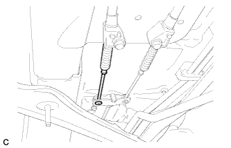
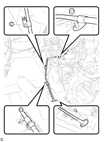
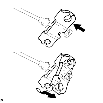
Connect the No. 3 parking brake cable assembly to the parking brake equalizer.
-
- Click here
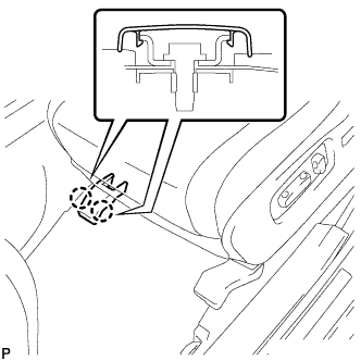
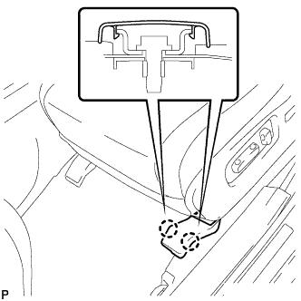
CONNECT NO. 2 PARKING BRAKE CABLE ASSEMBLY
Tip:Perform the same procedure as for the No. 3 parking brake cable assembly.
- Click here
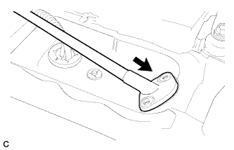
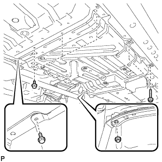
INSTALL REAR ENGINE SERVICE COVER ASSEMBLY
-
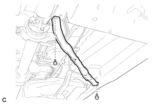
Install the rear engine service cover assembly with the 2 bolts.
-
- Click here
INSTALL CENTER FRONT FLOOR COVER
-
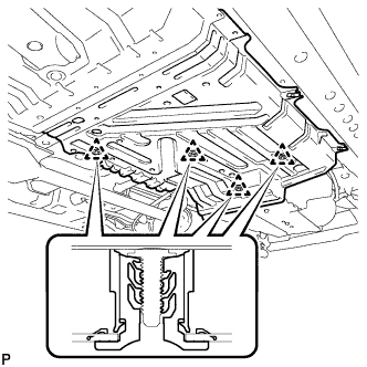
Engage the 4 clips to install the center front floor cover.
-
Install the 4 bolts, 2 screws, and the nut.
-
- Click here
INSTALL FRONT FLOOR FOOTREST (for LHD)
-
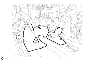
Engage the 2 clips to install the front floor footrest.
-
- Click here
INSTALL REAR NO. 1 AIR DUCT
-
Install the rear No. 1 air duct.
-
Engage the wire harness clamp.
-
- Click here
INSTALL REAR NO. 2 AIR DUCT
-
Install the rear No. 2 air duct with the clip.
-
Install the floor carpet.
-
- Click here
INSTALL FRONT NO. 1 CONSOLE BOX INSERT (for LHD)
-
Engage the claw and 2 guides.
-
Install the front No. 1 console box insert with the 3 screws <F> and 2 clips.
-
- Click here
INSTALL FRONT NO. 1 CONSOLE BOX INSERT (for RHD)
-
Engage the claw and 2 guides.
-
Install the front No. 1 console box insert with the 3 screws <F> and clip.
-
- Click here
INSTALL CONSOLE BOX ASSEMBLY (w/o Rear Air Conditioning System)
-
Engage the 6 claws.
-
Install the console box assembly with the 4 bolts and 2 screws.
-
- Click here
INSTALL CONSOLE BOX ASSEMBLY (w/ Rear Air Conditioning System)
-
Engage the 6 claws.
-
Connect the connector.
-
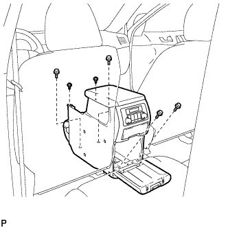
Install the console box assembly with the 4 bolts and 2 screws.
-
- Click here
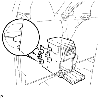
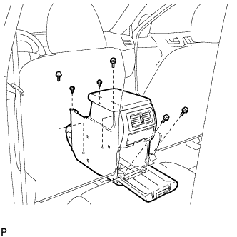
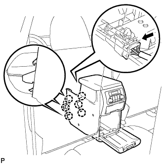
INSTALL LOWER REAR CONSOLE BOX
-
Install the lower rear console box.
-
- Click here
INSTALL NO. 2 CONSOLE BOX DUCT (w/o Rear Air Conditioning System)
-
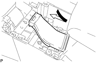
Install the No. 2 console box duct as shown in the illustration.
-
- Click here
INSTALL UPPER CONSOLE PANEL SUB-ASSEMBLY
-
Connect the connector.
-
Engage the 4 claws and 4 clips, and install the upper console panel sub-assembly.
-
- Click here
INSTALL CENTER INSTRUMENT CLUSTER FINISH PANEL ASSEMBLY (w/o Smart Entry and Start System)
-

Apply protective tape to the areas shown in the illustration.
-
Connect each connector.
-
Engage the 10 claws and 8 clips, and install the center instrument cluster finish panel assembly.
Note:Do not the damage the instrument panel safety pad assembly and lower instrument panel finish panel sub-assembly.
-
- Click here
INSTALL CENTER INSTRUMENT CLUSTER FINISH PANEL ASSEMBLY (w/ Smart Entry and Start System)
-
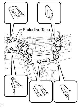
Apply protective tape to the areas shown in the illustration.
-
Connect each connector.
-
Engage the 10 claws and 8 clips, and install the center instrument cluster finish panel assembly.
Note:Do not the damage the instrument panel safety pad assembly and lower instrument panel finish panel sub-assembly.
-
- Click here
INSTALL NO. 1 AIR DUCT SUB-ASSEMBLY (for RHD)
-
Engage the 2 claws to install the No. 1 air duct sub-assembly.
-
- Click here
INSTALL LOWER CENTER PILLAR GARNISH LH
-
Engage the 2 claws and the 2 clips, and install the lower center pillar garnish LH.
-
- Click here
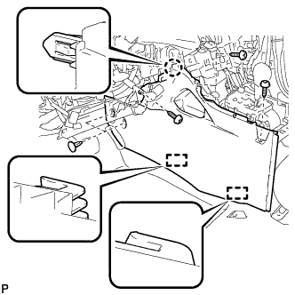
INSTALL REAR DOOR SCUFF PLATE LH
-
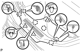
Engage the guide, 3 clips and 5 claws, and install the rear door scuff plate LH.
-
- Click here
INSTALL LOWER INSTRUMENT PANEL SUB-ASSEMBLY (for RHD)
Tip:This is symmetrical to the LHD model (Click here).
- Click here
INSTALL NO. 2 INSTRUMENT PANEL UNDER COVER SUB-ASSEMBLY (for RHD)
Tip:This is symmetrical to the LHD model (Click here).
- Click here
INSTALL COWL SIDE TRIM SUB-ASSEMBLY LH (for RHD)
Tip:Use the same procedure for the LHD model (Click here).
- Click here
INSTALL FRONT DOOR SCUFF PLATE LH (for RHD)
Tip:Use the same procedure for the LHD model (Click here).
- Click here
INSTALL DRIVER SIDE KNEE AIRBAG ASSEMBLY (for LHD)
-
Check that the ignition switch is off.
-
Check that the battery negative (-) cable is disconnected.
CAUTION:Wait for at least 90 seconds after disconnecting the cable to prevent airbag deployment.
-
Install the DLC3 to the driver side knee airbag assembly with the 2 claws.
-
Connect the connector to the driver side knee airbag assembly.
Note:When handling the airbag connector, take care not to damage the airbag wire harness.
-
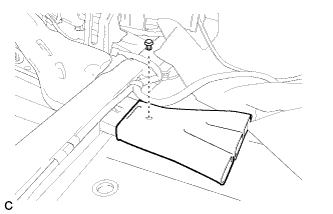
Support the driver side knee airbag assembly with one hand as shown in the illustration.
-
Temporarily install the driver side knee airbag assembly with the 2 hooks.
-
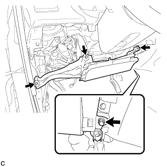
Install the driver side knee airbag assembly with the 4 bolts.
10 N*m 102 kgf*cm 7 ft.*lbf
-
- Click here
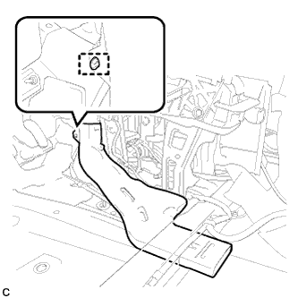
INSTALL LOWER INSTRUMENT PANEL FINISH PANEL SUB-ASSEMBLY (for LHD Manual Air Conditioning System)
-

Connect the hood lock control cable assembly.
-
Connect each connector.
-
Engage the 3 claws and 10 clips.
-
Install the lower instrument panel finish panel sub-assembly with the 2 bolts <B>.
-
- Click here
INSTALL LOWER INSTRUMENT PANEL FINISH PANEL SUB-ASSEMBLY (for LHD Automatic Air Conditioning System)
-

Connect the hood lock control cable assembly.
-
Connect each connector and the aspirator duct.
-

Engage the 3 claws and 10 clips.
-
Install the lower instrument panel finish panel sub-assembly with the 2 bolts <B>.
-
- Click here
INSTALL COWL SIDE TRIM SUB-ASSEMBLY LH (for LHD)
-

Engage the claw and clip, install the cowl side trim sub-assembly LH.
-
Install the clip.
-
- Click here
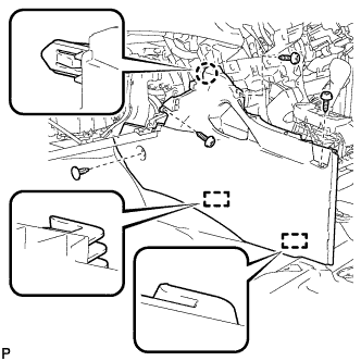
INSTALL FRONT DOOR SCUFF PLATE LH (for LHD)
-

Engage the guide and the 8 claws, and install the front door scuff plate LH.
-
- Click here
INSTALL DRIVER SIDE KNEE AIRBAG ASSEMBLY (for RHD)
Tip:This is symmetrical to the LHD model (Click here).
- Click here
INSTALL LOWER INSTRUMENT PANEL FINISH PANEL SUB-ASSEMBLY (for RHD Manual Air Conditioning System)
Tip:This is symmetrical to the LHD model (Click here).
- Click here
INSTALL LOWER INSTRUMENT PANEL FINISH PANEL SUB-ASSEMBLY (for RHD Automatic Air Conditioning System)
Tip:This is symmetrical to the LHD model (Click here).
- Click here
INSTALL COWL SIDE TRIM SUB-ASSEMBLY RH (for RHD)
Tip:This is symmetrical to the LHD model (Click here).
- Click here
INSTALL FRONT DOOR SCUFF PLATE RH (for RHD)
Tip:This is symmetrical to the LHD model (Click here).
- Click here
INSTALL FRONT SEAT ASSEMBLY LH (for Manual Seat)
-
Place the front seat assembly in the cabin.
Note:Be careful not to damage the vehicle body.
-
Connect the connectors under the seat.
-
Temporarily install the front seat assembly with the 4 bolts.
-
Lift up the seat track adjusting handle and move the seat to the rearmost position.
-
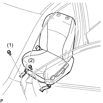
Tighten the 2 bolts on the front side of the seat.
37 N*m 377 kgf*cm 27 ft.*lbf Tip:Tighten the bolts in the order indicated in the illustration.
-
Lift up the seat track adjusting handle and move the seat to the foremost position.
-
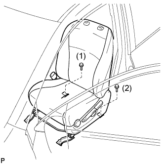
Tighten the 2 bolts on the rear side of the seat.
37 N*m 377 kgf*cm 27 ft.*lbf Tip:Tighten the bolts in the order indicated in the illustration.
-
- Click here
INSPECT FRONT SEAT SLIDE ADJUSTER LOCK (for Manual Seat)
-
During sliding operation of the front seat, check that the left and right adjusters move together smoothly and lock simultaneously.
If the seat adjusters do not lock simultaneously, loosen the bolts securing the seat to adjust the adjuster position.
-
- Click here
INSTALL REAR SEAT TRACK COVER LH (for Manual Seat)
-
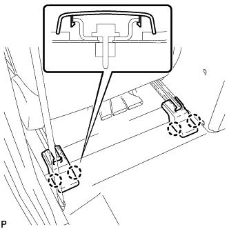
Engage the 4 claws and install the 2 rear seat track covers.
-
- Click here
INSTALL FRONT INNER SEAT TRACK COVER LH (for Manual Seat)
-
Lift up the seat track adjusting handle and move the seat to the rearmost position.
-
Engage the 2 claws and install the front inner seat track cover.
-
- Click here
INSTALL FRONT OUTER SEAT TRACK COVER LH (for Manual Seat)
-
Engage the 2 claws and install the front outer seat track cover.
-
- Click here
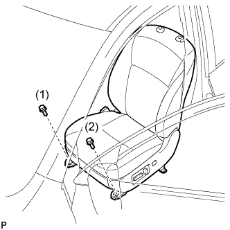
INSTALL FRONT SEAT HEADREST ASSEMBLY LH (for Manual Seat)
- Click here
INSTALL FRONT SEAT ASSEMBLY LH (for Power Seat)
-
Place the front seat assembly in the cabin.
Note:Be careful not to damage the vehicle body.
-
Connect the connectors under the seat.
-
Connect the cable to the negative (-) battery terminal.
Note:When reconnected the cable, some systems need to be initialized (Click here).
-
Temporarily install the front seat assembly with the 4 bolts.
-
Operate the power seat switch knob and move the seat to the rearmost position.
-
Tighten the 2 bolts on the front side of the seat.
37 N*m 377 kgf*cm 27 ft.*lbf Tip:Tighten the bolts in the order indicated in the illustration.
-
Operate the power seat switch knob and move the seat to the foremost position.
-
Tighten the 2 bolts on the rear side of the seat.
37 N*m 377 kgf*cm 27 ft.*lbf Tip:Tighten the bolts in the order indicated in the illustration.
-
- Click here
INSTALL REAR INNER SEAT TRACK COVER LH (for Power Seat)
-
Engage the 2 claws and install the rear inner seat track cover.
-
- Click here
INSTALL REAR OUTER SEAT TRACK COVER LH (for Power Seat)
-
Engage the 2 claws and install the rear outer seat track cover.
-
- Click here
INSTALL FRONT INNER SEAT TRACK COVER LH (for Power Seat)
-
Operate the power seat switch knob and move the seat to the rearmost position.
-
Engage the 2 claws and install the front inner seat track cover.
-
- Click here
INSTALL FRONT OUTER SEAT TRACK COVER LH (for Power Seat)
-
Engage the 2 claws and install the front outer seat track cover.
-
- Click here
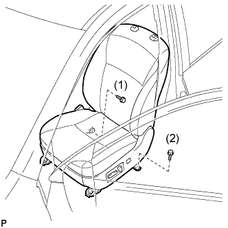
INSTALL FRONT SEAT HEADREST ASSEMBLY LH (for Power Seat)
- Click here
INSPECT FRONT SEAT ASSEMBLY LH (for Power Seat)
-
Inspect the power seat operation.
-
w/ Seat Heater System:
Check the seat heater operation.
-
Turn the ignition switch on (IG).
-
Turn the seat heater switch on.
-
Wait 5 minutes or more and confirm that the seat surface becomes warm.
-
-
- Click here
ADJUST PARKING BRAKE SHOE CLEARANCE AND PARKING BRAKE PEDAL TRAVEL (for LHD)
-
Remove the driver side knee airbag assembly (Click here).
-
Completely release the parking brake pedal.
-
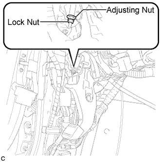
Loosen the lock nut and the adjusting nut to completely release the parking brake cable.
-
Remove the rear wheel.
-
Temporarily install the hub nuts.
-
Remove the shoe adjusting hole plug.
-
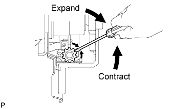
Turn the shoe adjuster and expand the shoe until the disc locks.
-
Turn and contract the shoe adjuster until the disc can rotate smoothly.
Standard Return 8 notches. -
Check that there is no brake drag against the shoe.
-
Install the shoe adjusting hole plug.
-
Turn the adjusting nut until the parking brake pedal travel is corrected to be within the specified range.
Parking brake pedal travel 8 to 10 notches at 300 N (31 kgf, 67 lbf) -
Using a wrench or an equivalent tool, hold the adjusting nut and tighten the lock nut.
7.0 N*m 71 kgf*cm 62 in.*lbf -
Operate the parking brake pedal 3 to 4 times, and check the parking brake pedal travel.
-
Check that there is no brake drag against the shoe.
-
Remove the hub nuts.
-
Install the rear wheel.
103 N*m 1050 kgf*cm 76 ft.*lbf -
Install the driver side knee airbag assembly (Click here).
-
- Click here
ADJUST PARKING BRAKE SHOE CLEARANCE AND PARKING BRAKE PEDAL TRAVEL (for RHD)
-
Remove the driver side knee airbag assembly (Click here).
-
Completely release the parking brake pedal.
-
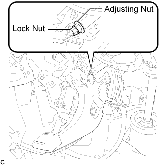
Loosen the lock nut and adjusting nut to completely release the parking brake cable.
-
Remove the rear wheel.
-
Temporarily install the hub nuts.
-
Remove the shoe adjusting hole plug.
-
Turn the shoe adjuster and expand the shoe until the disc locks.
-
Turn and contract the shoe adjuster until the disc can rotate smoothly.
Standard Return 8 notches. -
Check that there is no brake drag against the shoe.
-
Install the shoe adjusting hole plug.
-
Turn the adjusting nut until the parking brake pedal travel is corrected to be within the specified range.
Parking brake pedal travel 8 to 10 notches at 300 N (31 kgf, 67 lbf) -
Using a wrench or an equivalent tool, hold the adjusting nut and tighten the lock nut.
7.0 N*m 71 kgf*cm 62 in.*lbf -
Operate the parking brake pedal 3 to 4 times, and check the parking brake pedal travel.
-
Check that there is no brake drag against the shoe.
-
Remove the hub nuts.
-
Install the rear wheel.
103 N*m 1050 kgf*cm 76 ft.*lbf -
Install the driver side knee airbag assembly (Click here).
-
- Click here
CONNECT CABLE TO NEGATIVE BATTERY TERMINAL
Note:When disconnecting the cable, some systems need to be initialized after the cable is reconnected (Click here).
- Click here
INSPECT BRAKE WARNING LIGHT
-
When operating the parking brake pedal, check that the brake warning light illuminates.
Standard The brake warning light always illuminates at the first click.
-
- Click here
INSPECT SRS WARNING LIGHT
Tip: