PARKING BRAKE PEDAL REMOVAL
CAUTION:
Some of these service operations affect the SRS airbag system. Read the precautionary notices concerning the SRS airbag system before servicing the parking brake pedal Click here.
-
DISCONNECT CABLE FROM NEGATIVE BATTERY TERMINAL (for Manual Seat)
CAUTION:
Wait for 90 seconds after disconnecting the cable to prevent the airbag working.
Note
When disconnecting the cable, some systems need to be initialized after the cable is reconnected Click here.
-
REMOVE FRONT SEAT HEADREST ASSEMBLY LH (for Manual Seat)
-
REMOVE FRONT OUTER SEAT TRACK COVER LH (for Manual Seat)
-
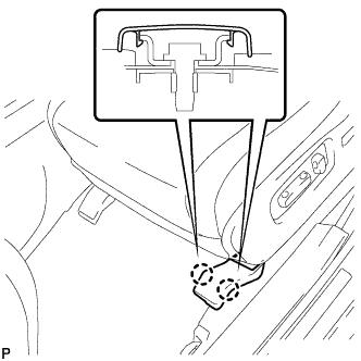
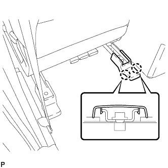
Lift up the seat track adjusting handle and move the seat to the rearmost position.
-
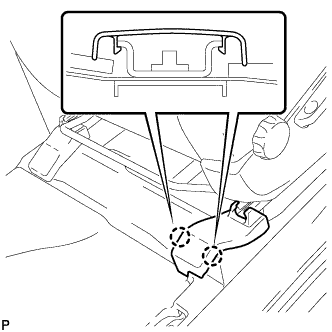
Disengage the 2 claws and remove the front outer seat track cover.
-
-
REMOVE FRONT INNER SEAT TRACK COVER LH (for Manual Seat)
-
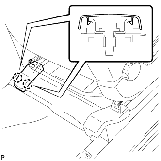
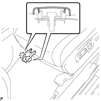
Disengage the 2 claws and remove the front inner seat track cover.
-
-
REMOVE REAR SEAT TRACK COVER LH (for Manual Seat)
-
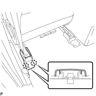
Lift up the seat track adjusting handle and move the seat to the foremost position.
-
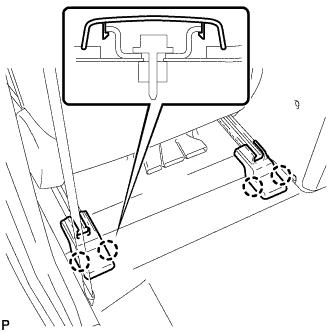
Disengage the 4 claws and remove the 2 rear seat track covers.
-
-
REMOVE FRONT SEAT ASSEMBLY LH (for Manual Seat)
-
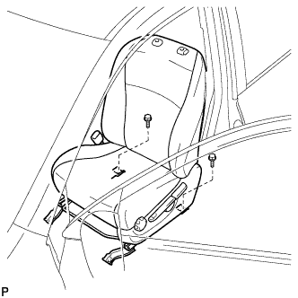
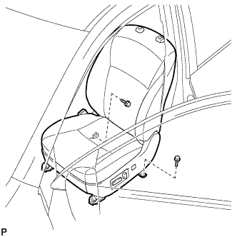
Remove the 2 bolts on the rear side of the seat.
-
Lift up the seat track adjusting handle and move the seat to the rearmost position.
-
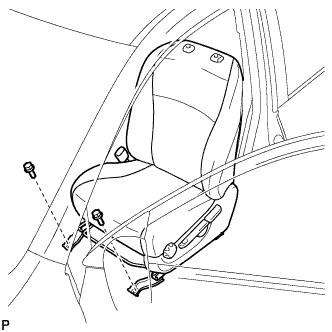
Remove the 2 bolts on the front side of the seat.
-
Lift up the seat track adjusting handle and move the seat to the center position. Also, operate the reclining adjuster release handle and move the seatback to the upright position.
-
Disconnect the connectors under the front seat assembly.
-
Remove the front seat assembly.
Note
Be careful not to damage the vehicle body.
-
-
REMOVE FRONT SEAT HEADREST ASSEMBLY LH (for Power Seat)
-
REMOVE FRONT OUTER SEAT TRACK COVER LH (for Power Seat)
-
Operate the power seat switch knob and move the seat to the rearmost position.
-
Disengage the 2 claws and remove the front outer seat track cover.
-
-
REMOVE FRONT INNER SEAT TRACK COVER LH (for Power Seat)
-
Disengage the 2 claws and remove the front inner seat track cover.
-
-
REMOVE REAR OUTER SEAT TRACK COVER LH (for Power Seat)
-
Operate the power seat switch knob and move the seat to the foremost position.
-
Disengage the 2 claws and remove the rear outer seat track cover.
-
-
REMOVE REAR INNER SEAT TRACK COVER LH (for Power Seat)
-
Disengage the 2 claws and remove the rear inner seat track cover.
-
-
REMOVE FRONT SEAT ASSEMBLY LH (for Power Seat)
-
Remove the 2 bolts on the rear side of the seat.
-
Operate the power seat switch knob and move the seat to the rearmost position.
-
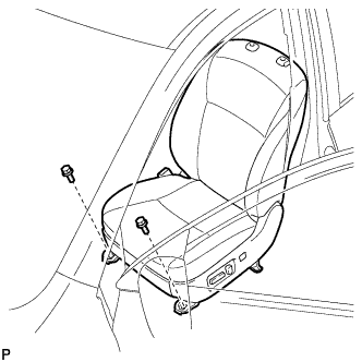
Remove the 2 bolts on the front side of the seat.
-
Operate the power seat switch knob and move the seat to the center position. Also, Operate the power seat switch knob and move the seatback to the upright position.
-
Disconnect the cable from the negative (-) battery terminal.
CAUTION:
-
Wait at least 90 seconds after disconnecting the cable from the negative (-) battery terminal to prevent the airbag and seat belt pretensioner from deploying Click here.
-
If the side airbag was deployed, replace the front seat assembly with a new one.
Note
When disconnecting the cable, some systems need to be initialized after the cable is reconnected Click here.
-
-
Disconnect each connector under the front seat assembly.
-
Remove the front seat assembly.
Note
Be careful not to damage the vehicle body.
-
-
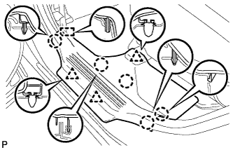
REMOVE FRONT DOOR SCUFF PLATE LH (for LHD)
-

Disengage the 8 claws and guide, and remove the front door scuff plate LH.
-
-
REMOVE COWL SIDE TRIM SUB-ASSEMBLY LH (for LHD)
-

Remove the clip.
-
Disengage the clip and claw, and remove the cowl side trim sub-assembly LH.
-
-
REMOVE LOWER INSTRUMENT PANEL FINISH PANEL SUB-ASSEMBLY (for LHD Manual Air Conditioning System)
-

Remove the 2 bolts <B>.
-
Disengage the 3 claws and 10 clips.
-
Disconnect each connector.
-
Disconnect the hood lock control cable assembly and remove the lower instrument panel finish panel sub-assembly.
-
-
REMOVE LOWER INSTRUMENT PANEL FINISH PANEL SUB-ASSEMBLY (for LHD Automatic Air Conditioning System)
-

Remove the 2 bolts <B>.
-
Disengage the 3 claws and 10 clips.
-

Disconnect each connector and the aspirator duct.
-
Disconnect the hood lock control cable assembly and remove the lower instrument panel finish panel sub-assembly.
-
-
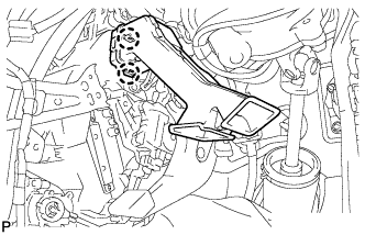
REMOVE DRIVER SIDE KNEE AIRBAG ASSEMBLY (for LHD)
-
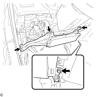
Remove the 4 bolts.
-
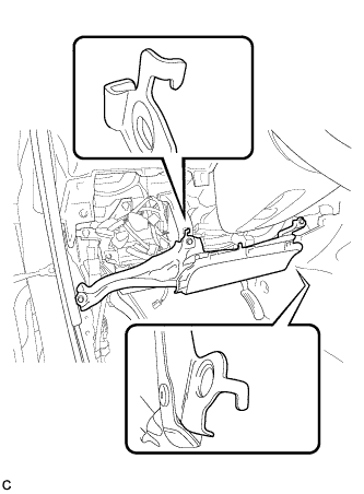
Disengage the 2 hooks.
-
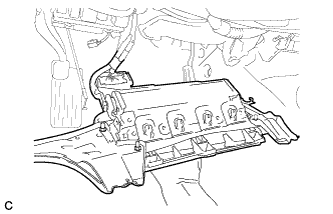
Pull out the driver side knee airbag assembly from the vehicle and support the driver side knee airbag assembly with one hand as shown in the illustration.
Note
When removing the driver side knee airbag assembly, do not pull the airbag wire harness.
-
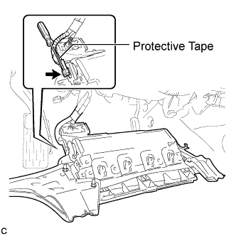
Using a screwdriver with the tip wrapped with protective tape, disconnect the driver side knee airbag connector.
Note
When handling the airbag connector, take care not to damage the airbag wire harness.
-
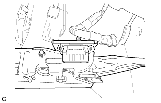
Disengage the 2 claws and separate the DLC3 from the driver side knee airbag assembly.
-
-
REMOVE FRONT DOOR SCUFF PLATE RH (for RHD)
Tech Tips
This is symmetrical to the LHD model Click here.
-
REMOVE COWL SIDE TRIM SUB-ASSEMBLY RH (for RHD)
Tech Tips
This is symmetrical to the LHD model Click here.
-
REMOVE LOWER INSTRUMENT PANEL FINISH PANEL SUB-ASSEMBLY (for RHD Manual Air Conditioning System)
Tech Tips
This is symmetrical to the LHD model Click here.
-
REMOVE LOWER INSTRUMENT PANEL FINISH PANEL SUB-ASSEMBLY (for RHD Automatic Air Conditioning System)
Tech Tips
This is symmetrical to the LHD model Click here.
-
REMOVE DRIVER SIDE KNEE AIRBAG ASSEMBLY (for RHD)
Tech Tips
This is symmetrical to the LHD model Click here.
-
REMOVE FRONT DOOR SCUFF PLATE LH (for RHD)
Tech Tips
Use the same procedure for the LHD model Click here.
-
REMOVE COWL SIDE TRIM SUB-ASSEMBLY LH (for RHD)
Tech Tips
Use the same procedure for the LHD model Click here.
-
REMOVE NO. 2 INSTRUMENT PANEL UNDER COVER SUB-ASSEMBLY (for RHD)
Tech Tips
This is symmetrical to the LHD model Click here.
-
REMOVE LOWER INSTRUMENT PANEL SUB-ASSEMBLY (for RHD)
Tech Tips
This is symmetrical to the LHD model Click here.
-
REMOVE REAR DOOR SCUFF PLATE LH
-
Disengage the 5 claws, 3 clips and guide, and remove the rear door scuff plate LH.
-
-
REMOVE LOWER CENTER PILLAR GARNISH LH
-
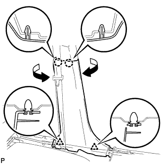
Disengage the 2 claws and 2 clips, and remove the lower center pillar garnish LH.
-
-
REMOVE NO. 1 AIR DUCT SUB-ASSEMBLY (for RHD)
-
Disengage the 2 claws and remove the No. 1 air duct sub-assembly.
-
-
REMOVE CENTER INSTRUMENT CLUSTER FINISH PANEL ASSEMBLY (w/o Smart Entry and Start System)
-
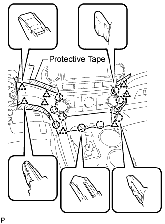
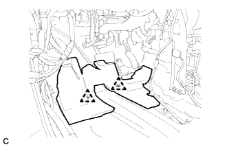
Apply protective tape to the areas shown in the illustration.
-
Using a moulding remover, disengage the 10 claws and 8 clips starting from the upper part of the center instrument cluster finish panel assembly.
Note
Do not pull on the small storage compartment lid. Doing so may cause damage.
-
Disconnect each connector and remove the center instrument cluster finish panel assembly.
-
-
REMOVE CENTER INSTRUMENT CLUSTER FINISH PANEL ASSEMBLY (w/ Smart Entry and Start System)
-
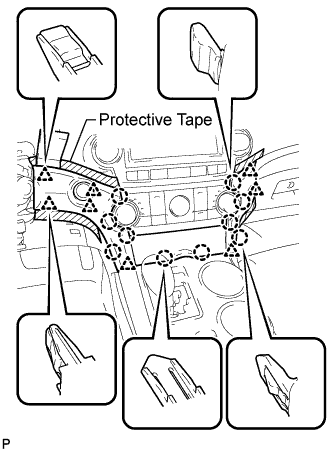
Apply protective tape to the areas shown in the illustration.
-
Using a moulding remover, disengage the 10 claws and 8 clips starting from the upper part of the center instrument cluster finish panel assembly.
Note
Do not pull on the small storage compartment lid. Doing so may cause damage.
-
Disconnect each connector and remove the center instrument cluster finish panel assembly.
-
-
REMOVE UPPER CONSOLE PANEL SUB-ASSEMBLY
-
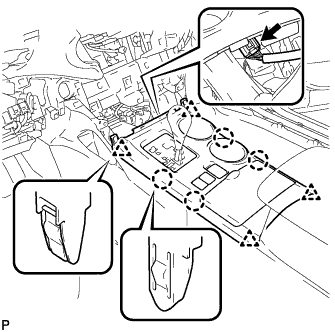
Disengage the 4 claws and 4 clips.
-
Disconnect the connector and remove the upper console panel sub-assembly.
-
-
REMOVE NO. 2 CONSOLE BOX DUCT (w/o Rear Air Conditioning System)
-
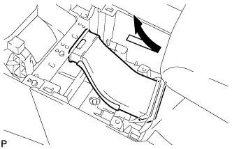
Remove the No. 2 console box duct as shown in the illustration.
-
-
REMOVE LOWER REAR CONSOLE BOX
-
Remove the lower rear console box.
-
-
REMOVE CONSOLE BOX ASSEMBLY (w/o Rear Air Conditioning System)
-
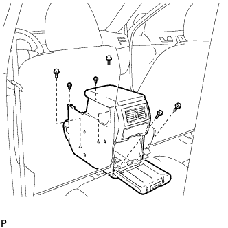
Remove the 4 bolts and 2 screws.
-
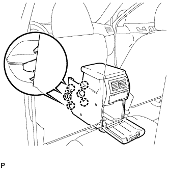
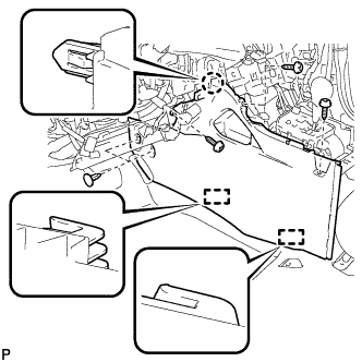
Disengage the 6 claws and remove the console box assembly.
-
-
REMOVE CONSOLE BOX ASSEMBLY (w/ Rear Air Conditioning System)
-
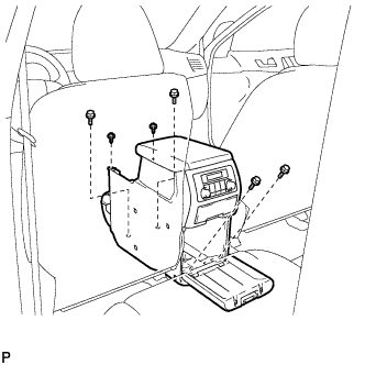
Remove the 4 bolts and 2 screws.
-
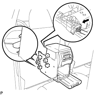
Disconnect the connector.
-
Disengage the 6 claws, and remove the console box assembly.
-
-
REMOVE FRONT NO. 1 CONSOLE BOX INSERT (for LHD)
-
Using a clip remover, remove the 2 clips.
-
Remove the 3 screws <E>.
-
Disengage the claw and 2 guides, and then remove the front No. 1 console box insert.
-
-
REMOVE FRONT NO. 1 CONSOLE BOX INSERT (for RHD)
-
Using a clip remover, remove the clip.
-
Remove the 3 screws <E>.
-
Disengage the claw and 2 guides, and then remove the front No. 1 console box insert.
-
-
REMOVE REAR NO. 2 AIR DUCT
-
Turn back the front floor carpet assembly.
-
Remove the clip and the rear No. 2 air duct.
-
-
REMOVE REAR NO. 1 AIR DUCT
-
Disengage the wire harness clamp.
-
Remove the rear No. 1 air duct.
-
-
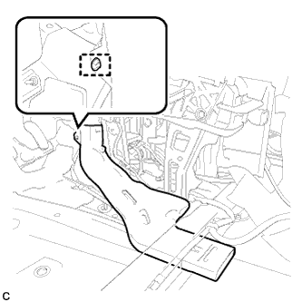
REMOVE FRONT FLOOR FOOTREST (for LHD)
-
Disengage the 2 clips to remove the front floor footrest.
-
-
LOOSEN ADJUSTING NUT (for LHD)
-
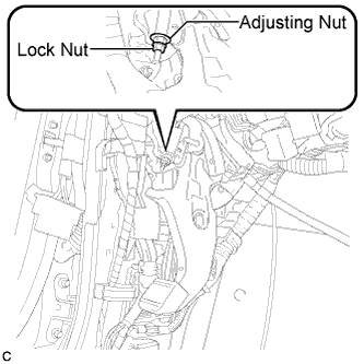
Remove the lock nut and loosen the adjusting nut.
-
-
LOOSEN ADJUSTING NUT (for RHD)
-
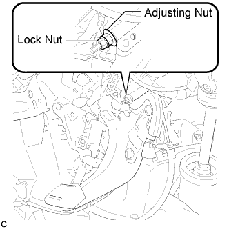
Remove the lock nut and loosen the adjusting nut.
-
-
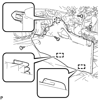
REMOVE CENTER FRONT FLOOR COVER
-
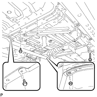
Remove the 4 bolts, 2 screws, and the nut.
-
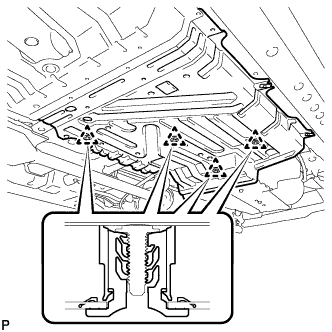
Disengage the 4 clips and remove the center front floor cover.
-
-
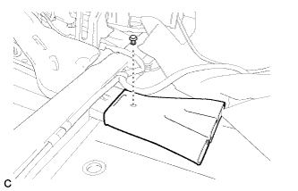
REMOVE REAR ENGINE SERVICE COVER ASSEMBLY
-
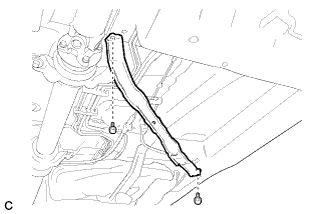
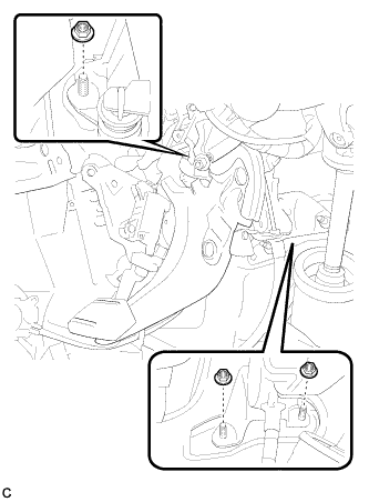
Remove the 2 bolts and the rear engine service cover assembly.
-
-
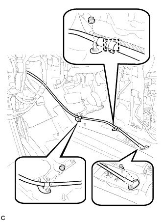
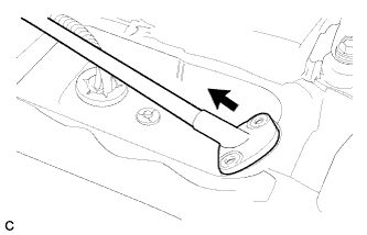
SEPARATE NO. 3 PARKING BRAKE CABLE ASSEMBLY
-
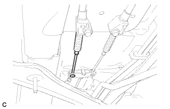
Separate the No. 3 parking brake cable assembly from the parking brake equalizer.
-
-
SEPARATE NO. 2 PARKING BRAKE CABLE ASSEMBLY
Tech Tips
Perform the same procedure as for the No. 3 parking brake cable assembly.
-
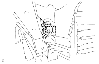
REMOVE PARKING BRAKE EQUALIZER
-
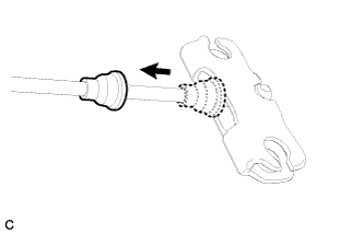
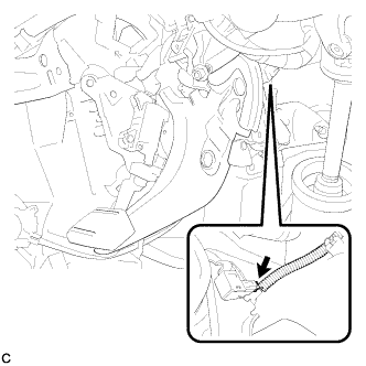
Slide the rubber boot as shown in the illustration.
-
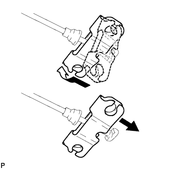
Remove the parking brake equalizer from the No. 1 parking brake cable assembly as shown in the illustration.
-
-
REMOVE INSTRUMENT PANEL JUNCTION BLOCK ASSEMBLY (for LHD)
-
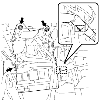
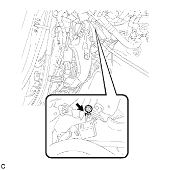
Separate the wire harness clamp from the instrument panel junction block assembly.
-
Disconnect the connectors from the instrument panel junction block assembly.
-
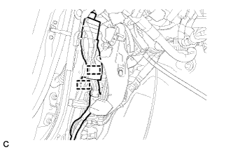
Remove the 3 nuts.
-
Move the instrument panel junction block assembly and disengage the wire harness clamp.
-
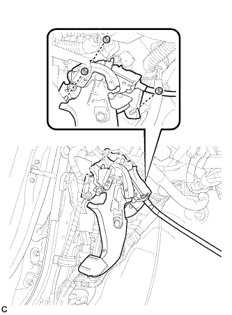
Disconnect the connectors from the back of the instrument panel junction block assembly.
-
Remove the instrument panel junction block assembly.
-
-
REMOVE PARKING BRAKE CONTROL PEDAL ASSEMBLY (for LHD)
-
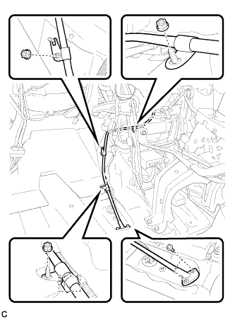
Remove the 2 bolts and 2 nuts, and separate the No. 1 parking brake cable assembly.
-
Remove the clamp.
-
Pull out the No. 1 parking brake cable assembly toward the cabin.
-
Disconnect the parking brake switch connector.
-
Disengage the 2 clamps to separate the wire harness clamp.
-
Remove the 3 nuts and the parking brake control pedal assembly.
-
-
REMOVE PARKING BRAKE CONTROL PEDAL ASSEMBLY (for RHD)
-
Remove the 2 bolts and 3 nuts, and separate the No. 1 parking brake cable assembly.
-
Remove the clamp.
-
Pull out the No. 1 parking brake cable assembly toward the cabin.
-
Disconnect the parking brake switch connector.
-
Remove the 3 nuts and the parking brake control pedal assembly.
-