BRAKE BOOSTER (for LHD) INSTALLATION
-
INSTALL BRAKE BOOSTER GASKET
-
Install a new brake booster gasket to the brake booster assembly.
-
-
INSTALL BRAKE BOOSTER ASSEMBLY
-
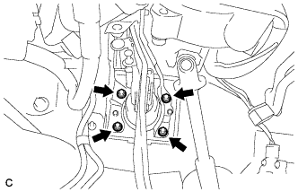
Install the brake booster assembly to the body and temporarily tighten the 4 nuts.
Note
Do not damage the brake lines.
Tech Tips
Fully tighten the 4 nuts after installing the brake master cylinder push rod clevis and push rod clevis lock nut.
-
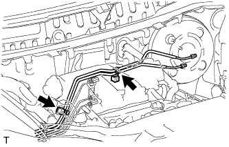
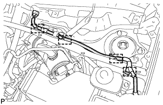
Engage the 2 clamps and install the 2 brake lines to the body.
Note
Be careful not to damage the brake lines or clamps. If any parts are damaged, replace them with new ones.
-
-
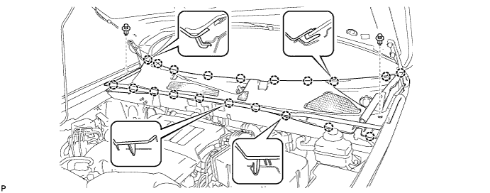
INSTALL ENGINE WIRE
-
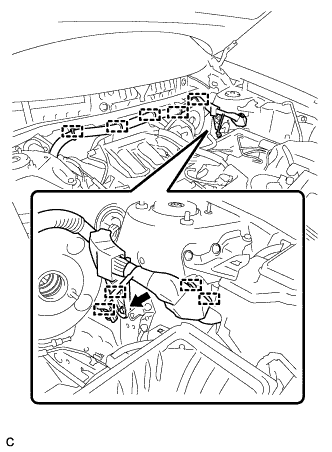
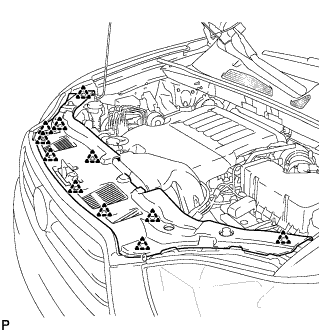
Engage the 9 clamps.
-
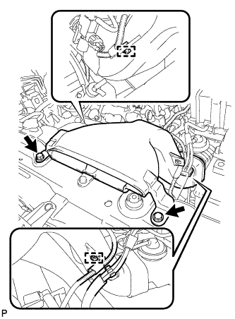
Install the engine wire to the body with the bolt.
- Torque:
- 8.4 N*m { 86 kgf*cm, 74 in.*lbf }
-
-
INSTALL ENGINE WIRE (w/ Security Horn)
-
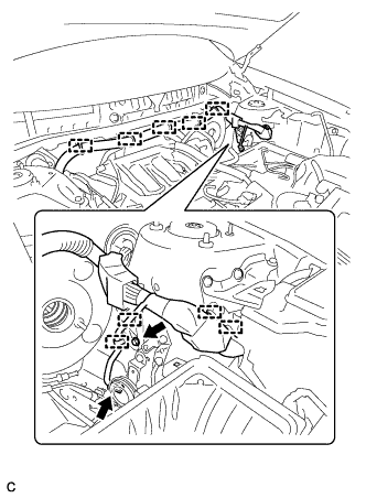
Engage the 9 clamps.
-
Connect the alarm horn connector and install the engine wire to the body with the bolt.
- Torque:
- 8.4 N*m { 86 kgf*cm, 74 in.*lbf }
-
-
INSTALL CHECK VALVE GROMMET
-
Install a new check valve grommet to the brake booster assembly.
-
-
INSTALL BRAKE VACUUM CHECK VALVE ASSEMBLY
-
Install the vacuum check valve assembly to the brake booster assembly.
-
-
CONNECT VACUUM HOSE
-
Connect the vacuum hose to the vacuum check valve and slide the clip.
-
-
INSTALL BRAKE MASTER CYLINDER PUSH ROD CLEVIS
-
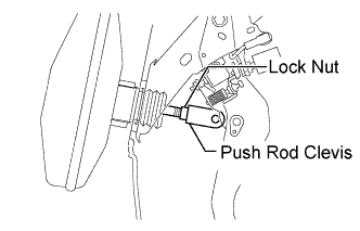
Install the push rod clevis lock nut and brake master cylinder push rod clevis to the brake booster assembly, and temporarily tighten the push rod clevis lock nut.
Note
Do not damage the brake lines.
Tech Tips
Fully tighten the lock nut after adjusting the brake pedal height.
-
Fully tighten the 4 nuts to install the brake booster assembly to the body.
- Torque:
- 13 N*m { 132 kgf*cm, 10 ft.*lbf }
-
-
CONNECT BRAKE MASTER CYLINDER PUSH ROD CLEVIS
-
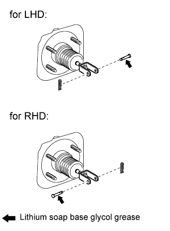
Apply lithium soap base glycol grease to the push rod pin.
-
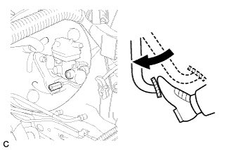
Connect the brake master cylinder push rod clevis to the brake pedal with the push rod pin, and install a new clip as shown in the illustration.
-
-
INSTALL BRAKE PEDAL RETURN SPRING
-
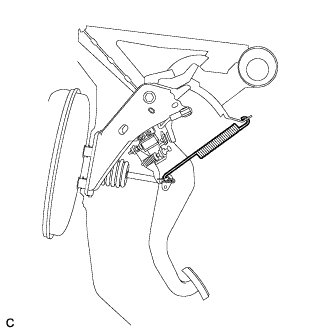
Install the brake pedal return spring between the instrument panel reinforcement and brake master cylinder push rod clevis.
-
-
INSTALL BRAKE MASTER CYLINDER SUB-ASSEMBLY
-
Install a new O-ring to the brake master cylinder sub-assembly.
-
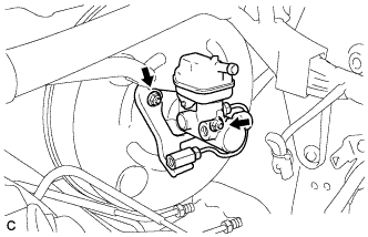
Install the brake master cylinder sub-assembly to the brake booster assembly with the 2 nuts.
- Torque:
- 13 N*m { 132 kgf*cm, 10 ft.*lbf }
Note
-
The master cylinder requires careful handling. Do not allow the master cylinder to receive any impact, such as from being dropped. Do not reuse a master cylinder that has been dropped.
-
Do not strike or pinch the master cylinder piston, and do not cause any damage to the master cylinder piston by any other means.
-
When installing the master cylinder to the brake booster, or when removing the master cylinder from the brake booster, make sure that the master cylinder is kept horizontal or its tip faces downward (the piston faces upward) to prevent the master cylinder piston from falling out.
-
Do not allow any foreign objects to contaminate the master cylinder piston. If a foreign object gets on the piston, remove it by using a shop rag or a piece of cloth and then apply an even layer of lithium soap based glycol grease around the circumference (sliding part) of the piston.
-
Do not use any other type of grease or fluid.
-
-
CONNECT BRAKE LINE
-
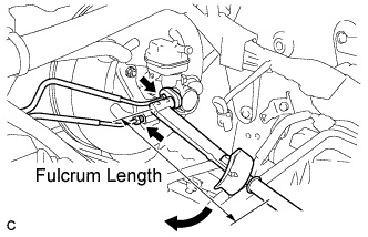
Using a union nut wrench (12 mm), connect the 2 brake lines to the brake master cylinder sub-assembly.
- Torque:
- without union nut wrench
- 20 N*m { 204 kgf*cm, 15 ft.*lbf }
- with union nut wrench
- 18 N*m { 184 kgf*cm, 13 ft.*lbf }
Note
-
Use a torque wrench with a fulcrum length of 250 mm (9.84 in.).
-
This torque value is effective when the union nut wrench is parallel to the torque wrench.
-
-
CONNECT NO. 1 RESERVOIR TUBE
-
Connect the No. 1 reservoir tube to the brake master cylinder reservoir assembly.
-
-
FILL BRAKE FLUID RESERVOIR
-
Fill the reservoir with brake fluid.
Brake Fluid SAE J1703 or FMVSS No. 116 DOT 3 Note
Make sure that there is sufficient brake fluid in the reservoir.
-
-
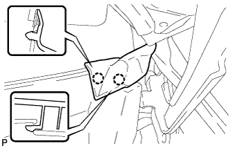
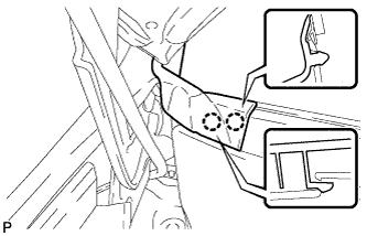
BLEED BRAKE MASTER CYLINDER
Note
-
If the master cylinder is reinstalled or if the reservoir becomes empty, bleed the master cylinder.
-
To prevent brake fluid from adhering, cover the painted surfaces with a shop rag or a piece of cloth.
-
Using a union nut wrench (12 mm), disconnect the 2 brake lines from the master cylinder.
-
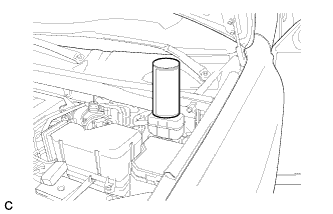
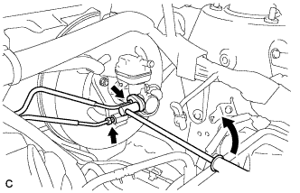
Slowly depress the brake pedal and hold it (*1).
-
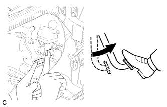
Cover the 2 outer holes with fingers, and release the brake pedal (*2).
-
Repeat (*1) and (*2) 3 or 4 times.
-
Using a union nut wrench (12 mm), connect the 2 brake lines to the master cylinder.
- Torque:
- w/o union nut wrench
- 20 N*m { 204 kgf*cm, 15 ft.*lbf }
- w/ union nut wrench
- 18 N*m { 184 kgf*cm, 13 ft.*lbf }
Note
-
Use a torque wrench with a fulcrum length of 250 mm (9.84 in.).
-
This torque value is effective when the union nut wrench is parallel to the torque wrench.
-
-
BLEED BRAKE LINE
Note
-
Bleed the brake line of the wheel farthest from the master cylinder first.
-
Add brake fluid to keep the level between the MIN and MAX lines of the reservoir while bleeding the brakes.
-
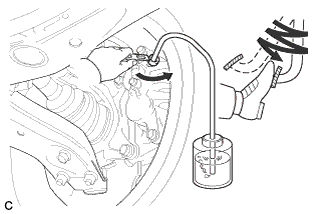
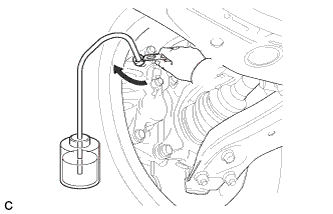
Connect a vinyl tube to the bleeder plug.
-
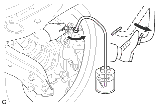
Depress the brake pedal several times, and then loosen the bleeder plug with the pedal depressed (*3).
-
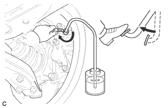
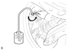
When fluid stops coming out, tighten the bleeder plug, and then release the brake pedal (*4).
-
Repeat (*3) and (*4) until all the air in the fluid is completely bled out.
-
Tighten the bleeder plug completely.
- Torque:
- 8.3 N*m { 85 kgf*cm, 73 in.*lbf }
-
Repeat the above procedure for each wheel to bleed the brake line.
-
-
BLEED BRAKE ACTUATOR
Note
After bleeding the brake system, if the specified height or feel of the brake pedal cannot be obtained, bleed the brake actuator assembly with the intelligent tester by following the procedure below.
-
Depress the brake pedal more than 20 times with the ignition switch off.
-
Connect the intelligent tester to the DLC3, and then turn the ignition switch on (IG).
Note
Do not start the engine.
-
Turn the intelligent tester on and select "AIR BLEEDING" on the screen.
Note
-
Refer to the intelligent tester operator's manual for further details.
-
Bleed the air by following the steps displayed on the intelligent tester.
-
-
Bleed the air according to "Step 1: Increase" on the intelligent tester display.
Note
-
Make sure that the master cylinder reservoir tank does not run out of brake fluid.
-
Add brake fluid to keep the level between the MIN and MAX lines of the reservoir while bleeding the brakes.
-
Connect a vinyl tube to either one of the bleeder plugs.
-
Depress the brake pedal several times, and then loosen the bleeder plug connected to the vinyl tube with the pedal depressed (*5).
-
When fluid stops coming out, tighten the bleeder plug, and then release the brake pedal (*6).
-
Repeat (*5) and (*6) until all the air in the fluid is completely bled out.
-
Tighten the bleeder plug completely.
- Torque:
- 8.3 N*m { 85 kgf*cm, 73 in.*lbf }
-
Repeat the above procedure for the rest of the wheels to bleed the brake lines.
-
-
Bleed the suction line according to "Step 2: Inhalation" on the intelligent tester display.
Note
-
Bleed the suction line by following the steps displayed on the intelligent tester.
-
Add brake fluid to keep the level between the MIN and MAX lines of the reservoir while bleeding the brakes.
-
Connect a vinyl tube to the bleeder plug at the right front wheel or the right rear wheel and loosen the bleeder plug.
-
Operate the brake actuator assembly to bleed the air using the intelligent tester (*7).
Note
-
During this step, be sure to release the brake pedal.
-
The actuator operation stops automatically in 4 seconds.
-
-
Check that the actuator operation has stopped by referring to the intelligent tester display, and tighten the bleeder plug (*8).
-
Repeat (*7) and (*8) until all the air in the fluid is completely bled out.
-
Tighten the bleeder plug completely.
- Torque:
- 8.3 N*m { 85 kgf*cm, 73 in.*lbf }
-
For the rest of the wheels, bleed the air in the same way as stated in the above procedure.
- Torque:
- 8.3 N*m { 85 kgf*cm, 73 in.*lbf }
-
-
Bleed the pressure reduction line according to "Step 3: Decrease" on the intelligent tester display.
Note
-
Bleed the pressure reduction line by following the steps displayed on the intelligent tester.
-
Add brake fluid to keep the level between the MIN and MAX lines of the reservoir while bleeding the brakes.
-
Connect a vinyl tube to either one of the bleeder plugs.
-
Loosen the bleeder plug (*9).
-
While keeping the brake pedal fully depressed, operate the brake actuator assembly using the intelligent tester.
Note
-
The actuator operation stops automatically in 4 seconds. When performing this procedure continuously, an interval of at least 20 seconds is required.
-
After the operation is completed, the brake pedal goes down slightly. This is a normal phenomenon when the solenoid opens.
-
During this procedure, the pedal seems heavy, but completely depress it so that the brake fluid comes out from the bleeder plug.
-
Be sure to keep the brake pedal depressed. Never depress and release the pedal repeatedly.
-
-
Tighten the bleeder plug, and then release the brake pedal (*10).
-
Repeat steps (*9) to (*10) until all the air in the fluid is completely bled out.
-
Tighten the bleeder plug completely.
- Torque:
- 8.3 N*m { 85 kgf*cm, 73 in.*lbf }
-
Repeat the above procedures for the rest of the brakes to bleed the brake line.
-
-
Bleed the brake lines again according to "Step 4: Increase" on the intelligent tester display.
Note
-
Bleed the air by following the steps displayed on the intelligent tester.
-
Add brake fluid to keep the level between the MIN and MAX lines of the reservoir while bleeding the brakes.
-
Connect a vinyl tube to either one of the bleeder plugs.
-
Depress the brake pedal several times, and then loosen the bleeder plug connected to the vinyl tube with the pedal depressed (*11).
-
When fluid stops coming out, tighten the bleeder plug, and then release the brake pedal (*12).
-
Repeat (*11) and (*12) until all the air in the fluid is completely bled out.
-
Tighten the bleeder plug completely.
- Torque:
- 8.3 N*m { 85 kgf*cm, 73 in.*lbf }
-
Repeat the above procedures for each brake to bleed the brake lines.
-
-
Finish "AIR BLEEDING" on the intelligent tester, and then turn off the tester.
-
Disconnect the intelligent tester from the DLC3.
-
Turn the ignition switch off.
-
-
INSPECT FOR BRAKE FLUID LEAK
-
INSPECT FLUID LEVEL
-
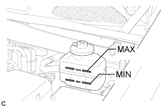
Check the fluid level.
If brake fluid level is lower than the MIN line, check for leaks and inspect the disc brake pads. If necessary, refill the reservoir with brake fluid to the MAX line after repair or replacement.
Brake Fluid SAE J1703 or FMVSS No. 116 DOT 3
-
-
INSPECT AND ADJUST BRAKE PEDAL HEIGHT
-
Check the brake pedal height.
-
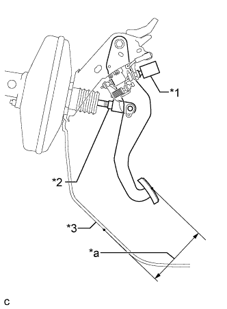
Text in Illustration *1 Stop Light Switch Assembly *2 Clevis Lock Nut *3 Front Floor Footrest (for LHD) No. 2 Dash Panel Insulator Pad (for RHD) *a Brake Pedal Height Turn back the carpet.
-
Measure the shortest distance between the brake pedal surface and front floor footrest (for LHD) or No. 2 dash panel insulator pad (for RHD).
Pedal height (for LHD: from front floor footrest, for RHD: from No. 2 dash panel insulator pad) Model Specified Condition LHD 148.8 to 158.8 mm (5.858 to 6.252 in.) RHD 165.9 to 175.9 mm (6.531 to 6.925 in.)
-
-
Adjust the brake pedal height.
-
Disconnect the stop light switch connector.
-
Remove the stop light switch assembly.
-
Loosen the push rod clevis lock nut.
-
Adjust the brake pedal height by turning the push rod.
-
Tighten the push rod clevis lock nut.
- Torque:
- 26 N*m { 265 kgf*cm, 19 ft.*lbf }
-
Install and adjust the stop light switch Click here.
Note
Do not depress the brake pedal.
-
Connect the stop light switch connector.
-
-
-
INSPECT BRAKE PEDAL FREE PLAY
-
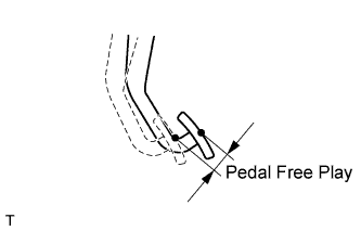
Stop the engine. Depress the pedal several times until no vacuum is left in the brake booster. Release the brake pedal.
-
Depress the pedal until a slight resistance is felt. Measure the distance as shown in the illustration.
Pedal free play 1.0 to 6.0 mm (0.039 to 0.236 in.) If the pedal free play is not as specified, check the stop light switch clearance Click here. If the pedal free play is as specified, proceed to the "INSPECT BRAKE PEDAL RESERVE DISTANCE" procedure.
-
-
INSPECT BRAKE PEDAL RESERVE DISTANCE
Tech Tips
Measure the distance at the same point used for the brake pedal height inspection.
-
Release the parking brake.
-
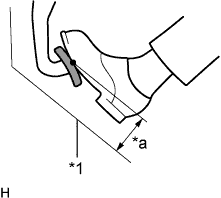
Text in Illustration *1 Front Floor Footrest (for LHD) No. 2 Dash Panel Insulator Pad (for RHD) *a Pedal Reserve Distance With the engine running, depress the brake pedal and measure the pedal reserve distance as shown in the illustration.
Pedal reserve distance at 500 N (51 kgf, 112 lbf) (for LHD: from front floor footrest, for RHD: from No. 2 dash panel insulator pad) Model Specified Condition LHD 84.4 mm (3.32 in.) RHD 97.8 mm (3.85 in.) If the distance is not as specified, troubleshoot the brake system Click here.
-
-
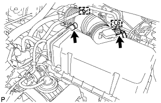
INSTALL CHARCOAL CANISTER ASSEMBLY
-
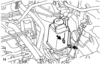
Install the charcoal canister assembly with the 2 bolts.
- Torque:
- 26.5 N*m { 270 kgf*cm, 20 ft.*lbf }
-
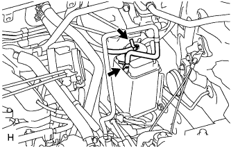
Connect the 2 hoses.
-
-
INSTALL AIR CLEANER CASE SUB-ASSEMBLY
-
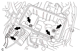
Install the air cleaner case with the 3 bolts.
- Torque:
- 5.0 N*m { 51 kgf*cm, 44 in.*lbf }
-
Connect the hose and connector.
-
-
INSTALL AIR CLEANER FILTER ELEMENT SUB-ASSEMBLY
-
Install the air cleaner filter element sub-assembly.
-
-
INSTALL AIR CLEANER CAP SUB-ASSEMBLY
-
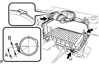
Install the air cleaner filter element, align the groove on the air cleaner hose with the throttle body alignment tab and tighten the clamp as shown in the illustration.
Tech Tips
-
A = 30°
-
B = 11 to 14 mm (0.433 in. to 0.551 in.)
-
-
Install the air cleaner cap with the 2 bolts and clips.
- Torque:
- 5.0 N*m { 51 kgf*cm, 44 in.*lbf }
-
Connect the 3 vacuum hoses.
-
Connect the mass air flow meter connector.
-
Connect the No. 2 ventilation hose and fuel vapor feed hose assembly.
-
-
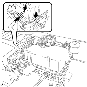
INSTALL NO. 2 AIR CLEANER INLET
-
Install the No. 2 air cleaner inlet with the 2 bolts.
- Torque:
- 7.0 N*m { 71 kgf*cm, 62 in.*lbf }
-
Connect the 2 vacuum hoses and harness clamps.
-
-
INSTALL COOL AIR INTAKE DUCT SEAL
-
Install the cool air intake duct seal with the 11 clips.
-
-
INSTALL OUTER COWL TOP PANEL SUB-ASSEMBLY
-
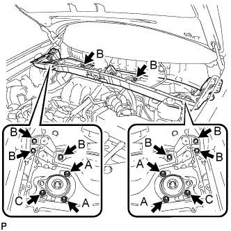
Install the outer cowl top panel sub-assembly with the 8 bolts and 6 nuts.
- Torque:
- Nut A
- 85 N*m { 866 kgf*cm, 63 ft.*lbf }
- Bolt B
- 8.8 N*m { 90 kgf*cm, 78 in.*lbf }
- Nut C
- 8.8 N*m { 90 kgf*cm, 78 in.*lbf }
-
Engage the 4 clamps.
-
-
INSTALL WINDSHIELD WIPER MOTOR AND LINK
-
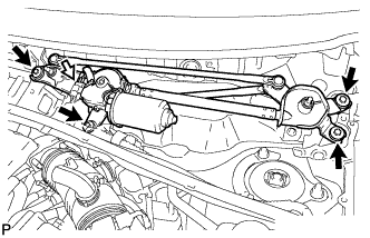
Install the windshield wiper motor and link assembly with the 4 bolts.
- Torque:
- 7.0 N*m { 71 kgf*cm, 62 in.*lbf }
-
Connect the connector.
-
-
INSTALL COWL TOP VENTILATOR LOUVER SUB-ASSEMBLY
-
Engage the 20 claws.
-
Install the cowl top ventilator louver sub-assembly with the 2 clips.
-
Engage the 2 claws and connect the front fender to cowl side seal LH.
-
Engage the 2 claws and connect the front fender to cowl side seal RH.
-
-
INSTALL FRONT WIPER ARM AND BLADE ASSEMBLY RH
-
Operate the wiper and stop the windshield wiper motor at the automatic stop position.
-
When reinstalling:
-
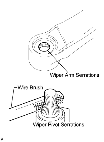
Clean the wiper arm serrations.
-
Clean the wiper pivot serrations with a wire brush.
-
-
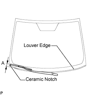
Install the front wiper arm and blade assembly RH with the nut to the position shown in the illustration.
- Torque:
- 24 N*m { 245 kgf*cm, 18 ft.*lbf }
Tech Tips
Hold the wiper arm by hand when tightening the nut.
Area Measurement A 25.6 mm (1.00 in.)
-
-
INSTALL FRONT WIPER ARM AND BLADE ASSEMBLY LH
-
Operate the wiper and stop the windshield wiper motor at the automatic stop position.
-
When reinstalling:
-
Clean the wiper arm serrations.
-
Clean the wiper pivot serrations with a wire brush.
-
-
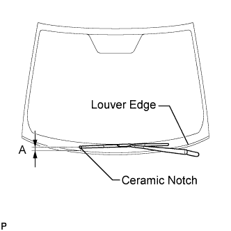
Install the front wiper arm and blade assembly LH with the nut to the position shown in the illustration.
- Torque:
- 24 N*m { 245 kgf*cm, 18 ft.*lbf }
Tech Tips
Hold the wiper arm by hand when tightening the nut.
Area Measurement A 31.9 mm (1.26 in.) -
Operate the front wipers while spraying washer fluid onto the windshield glass. Make sure that the front wipers function properly and the wipers do not come into contact with the vehicle body.
-