BRAKE PEDAL INSTALLATION
-
INSTALL BRAKE PEDAL SUPPORT SUB-ASSEMBLY (for LHD)
-
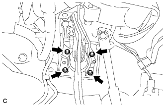
Install the brake pedal support sub-assembly with the 4 nuts.
- Torque:
- 13 N*m { 132 kgf*cm, 10 ft.*lbf }
-
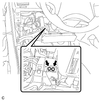
Install the brake pedal support sub-assembly to the instrument panel reinforcement with the 2 bolts.
- Torque:
- 35 N*m { 357 kgf*cm, 26 ft.*lbf }
-
Connect the brake pedal load sensing switch connector and engage the clamp.
-
-
INSTALL BRAKE PEDAL SUPPORT SUB-ASSEMBLY (for RHD)
-
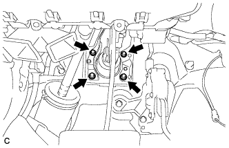
Install the brake pedal support sub-assembly with the 4 nuts.
- Torque:
- 13 N*m { 132 kgf*cm, 10 ft.*lbf }
-
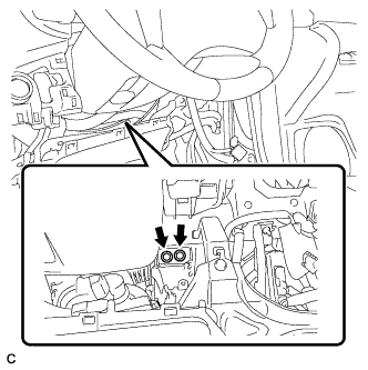
Install the brake pedal support sub-assembly to the instrument panel reinforcement with the 2 bolts.
- Torque:
- 35 N*m { 357 kgf*cm, 26 ft.*lbf }
-
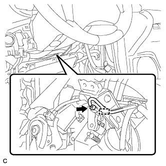
Connect the brake pedal load sensing switch connector and engage the clamp.
-
-
CONNECT BRAKE MASTER CYLINDER PUSH ROD CLEVIS
-
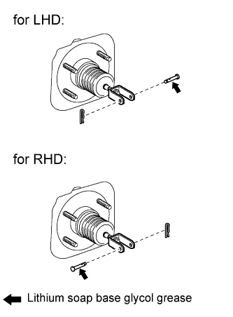
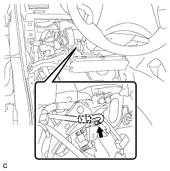
Apply lithium soap base glycol grease to the push rod pin.
-
Connect the brake master cylinder push rod clevis to the brake pedal with the push rod pin, and install a new clip as shown in the illustration.
-
-
INSTALL BRAKE PEDAL RETURN SPRING
-
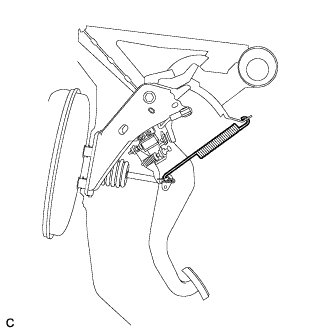
Install the brake pedal return spring between the instrument panel reinforcement and brake master cylinder push rod clevis.
-
-
INSTALL STOP LIGHT SWITCH ASSEMBLY
-
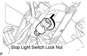
Temporarily install the stop light switch assembly with the stop light switch lock nut.
-
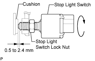
Turn the stop light switch assembly so that the clearance between the nut end and stop light switch cushion is between 0.5 to 2.4 mm (0.020 to 0.095 in.).
-
Tighten the stop light switch lock nut.
- Torque:
- 17 N*m { 173 kgf*cm, 12 ft.*lbf }
-
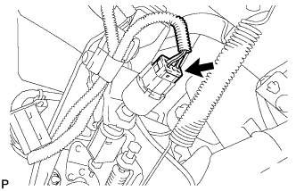
Connect the connector.
-
-
INSPECT AND ADJUST BRAKE PEDAL HEIGHT
-
Check the brake pedal height.
-
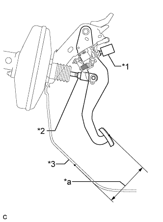
Text in Illustration *1 Stop Light Switch Assembly *2 Clevis Lock Nut *3 Front Floor Footrest (for LHD) No. 2 Dash Panel Insulator Pad (for RHD) *a Brake Pedal Height Turn back the carpet.
-
Measure the shortest distance between the brake pedal surface and front floor footrest (for LHD) or No. 2 dash panel insulator pad (for RHD).
Pedal height (for LHD: from front floor footrest, for RHD: No. 2 dash panel insulator pad) Model Specified Condition LHD 148.8 to 158.8 mm (5.858 to 6.252 in.) RHD 165.9 to 175.9 mm (6.531 to 6.925 in.)
-
-
Adjust the brake pedal height.
-
Disconnect the stop light switch connector.
-
Remove the stop light switch assembly.
-
Loosen the push rod clevis lock nut.
-
Adjust the brake pedal height by turning the push rod.
-
Tighten the push rod clevis lock nut.
- Torque:
- 26 N*m { 265 kgf*cm, 19 ft.*lbf }
-
Install and adjust the stop light switch Click here.
Note
Do not depress the brake pedal.
-
Connect the stop light switch connector.
-
-
-
INSPECT BRAKE PEDAL FREE PLAY
-
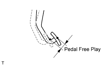
Stop the engine. Depress the pedal several times until no vacuum is left in the brake booster. Release the brake pedal.
-
Depress the pedal until a slight resistance is felt. Measure the distance as shown in the illustration.
Pedal free play 1.0 to 6.0 mm (0.039 to 0.236 in.) If the pedal free play is not as specified, check the stop light switch clearance Click here. If the pedal free play is as specified, proceed to the "INSPECT BRAKE PEDAL RESERVE DISTANCE" procedure.
-
-
INSPECT BRAKE PEDAL RESERVE DISTANCE
Tech Tips
Measure the distance at the same point used for the brake pedal height inspection.
-
Release the parking brake.
-
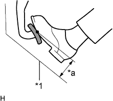
Text in Illustration *1 Front Floor Footrest (for LHD) No. 2 Dash Panel Insulator Pad (for RHD) *a Pedal Reserve Distance With the engine running, depress the brake pedal and measure the pedal reserve distance as shown in the illustration.
Pedal reserve distance at 500 N (51 kgf, 112 lbf) (for LHD: from front floor footrest, for RHD: from No. 2 dash panel insulator pad) Model Specified Condition LHD 84.4 mm (3.32 in.) RHD 97.8 mm (3.85 in.) If the distance is not as specified, troubleshoot the brake system Click here.
-
-
INSTALL LOWER INSTRUMENT PANEL FINISH PANEL SUB-ASSEMBLY (for Manual Air Conditioning System)
-

Connect the hood lock control cable assembly.
-
Connect each connector.
-
Engage the 3 claws and 10 clips.
-
Install the lower instrument panel finish panel sub-assembly with the 2 bolts <B>.
-
-
INSTALL LOWER INSTRUMENT PANEL FINISH PANEL SUB-ASSEMBLY (for Automatic Air Conditioning System)
-

Connect the hood lock control cable assembly.
-
Connect each connector and the aspirator duct.
-

Engage the 3 claws and 10 clips.
-
Install the lower instrument panel finish panel sub-assembly with the 2 bolts <B>.
-
-
INSTALL COWL SIDE TRIM SUB-ASSEMBLY LH
-

Engage the claw and clip, install the cowl side trim sub-assembly LH.
-
Install the clip.
-
-
INSTALL FRONT DOOR SCUFF PLATE LH
-

Engage the guide and the 8 claws, and install the front door scuff plate LH.
-