- Click here
INSTALL BRAKE MASTER CYLINDER PUSH ROD CLEVIS
-
Install the brake master cylinder push rod clevis and push rod clevis lock nut to the brake booster assembly, and temporarily tighten the push rod clevis lock nut.
Tip:Fully tighten the lock nut when adjusting the brake pedal height.
-
- Click here
INSTALL BRAKE BOOSTER GASKET
-
Install a new brake booster gasket to the brake booster assembly.
-
- Click here
INSTALL BRAKE BOOSTER ASSEMBLY
-
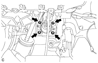
Install the brake booster assembly to the body with the 4 nuts.
13 N*m 132 kgf*cm 10 ft.*lbf Note:Do not damage the brake lines.
-
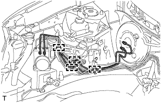
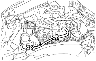
Engage the 4 clamps and install the 2 brake lines to the body.
Note:Be careful not to damage the brake lines or clamps. If any parts are damaged, replace them with new ones.
-
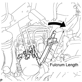
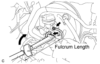
Using a union nut wrench (12 mm), connect the 2 brake lines to the brake actuator.
without union nut wrench 20 N*m 204 kgf*cm 15 ft.*lbf with union nut wrench 18 N*m 184 kgf*cm 13 ft.*lbf Note:
-
Use a torque wrench with a fulcrum length of 250 mm (9.84 in.).
-
This torque value is effective when the union nut wrench is parallel to the torque wrench.
-
-
- Click here
INSTALL NO. 1 COOLER REFRIGERANT SUCTION PIPE (w/o Rear Air Conditioning System)
-
Remove the attached vinyl tape from the pipe.
-
Sufficiently apply compressor oil to the O-rings of the tube ends.
Compressor oil ND-OIL 8 or equivalent -
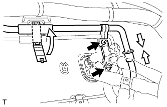
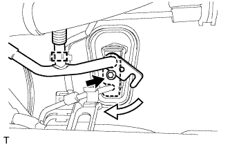
Connect the No. 1 cooler refrigerant suction pipe to the air conditioning unit and move the hook connector as shown in the illustration.
-
Install the bolt to secure the hook connector.
9.8 N*m 100 kgf*cm 87 in.*lbf -
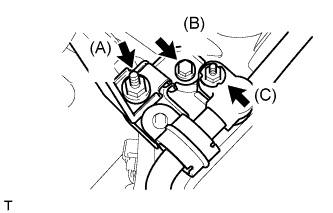
Connect the suction hose sub-assembly to the No. 1 cooler refrigerant suction pipe with the nut (C).
9.8 N*m 100 kgf*cm 87 in.*lbf -
Install the suction hose bracket to the body with the bolt (B).
9.8 N*m 100 kgf*cm 87 in.*lbf -
Install the discharge tube bracket to the suction hose bracket with the nut (A).
9.8 N*m 100 kgf*cm 87 in.*lbf -
Engage the 2 clamps to install the No. 1 cooler refrigerant suction pipe.
-
- Click here
INSTALL NO. 1 COOLER REFRIGERANT SUCTION PIPE (w/ Rear Air Conditioning System)
-
Remove the attached vinyl tape from the pipe.
-
Sufficiently apply compressor oil to the O-rings of the tube ends.
Compressor oil ND-OIL 8 or equivalent -
Connect the No. 1 cooler refrigerant suction pipe to the cooler refrigerant suction pipe A.
-
Install the nut and screw, and engage the clamp.
Nut 9.8 N*m 100 kgf*cm 87 in.*lbf -
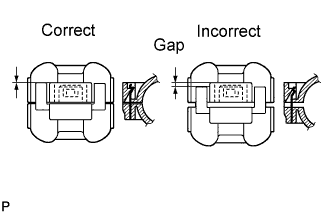
Engage the piping clamp to the No. 1 cooler refrigerant suction pipe and the cooler refrigerant suction pipe A.
Note:After connection, check the fitting of the piping clamp as shown in the illustration.
-
Connect the No. 1 cooler refrigerant suction pipe to the air conditioning unit and move the hook connector as shown in the illustration.
-
Engage the clamp and install the bolt to secure the hook connector.
9.8 N*m 100 kgf*cm 87 in.*lbf -
Connect the suction hose sub-assembly to the No. 1 cooler refrigerant suction pipe with the nut (C).
9.8 N*m 100 kgf*cm 87 in.*lbf -
Install the suction hose bracket to the body with the bolt (B).
9.8 N*m 100 kgf*cm 87 in.*lbf -
Install the discharge tube bracket to the suction hose bracket with the nut (A).
9.8 N*m 100 kgf*cm 87 in.*lbf -
Engage the 2 clamps to install the No. 1 cooler refrigerant suction pipe.
-
- Click here
INSTALL CHECK VALVE GROMMET
-
Install a new check valve grommet to the brake booster assembly.
-
- Click here
INSTALL BRAKE VACUUM CHECK VALVE ASSEMBLY
-
Install the vacuum check valve assembly to the brake booster assembly.
-
- Click here
CONNECT VACUUM HOSE
-
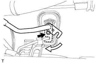
Connect the vacuum hose to the vacuum check valve and slide the clip.
-
- Click here
CONNECT BRAKE MASTER CYLINDER PUSH ROD CLEVIS
-
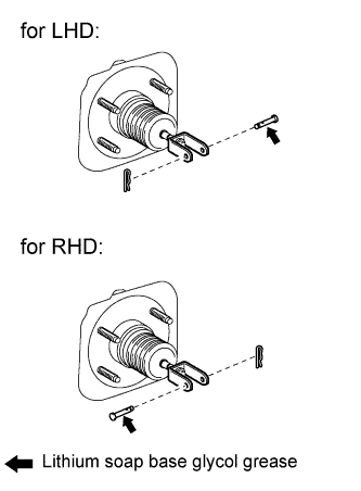
Apply lithium soap base glycol grease to the push rod pin.
-
Connect the brake master cylinder push rod clevis to the brake pedal with the push rod pin, and install a new clip as shown in the illustration.
-
- Click here
INSTALL BRAKE PEDAL RETURN SPRING
-
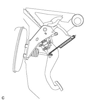
Install the brake pedal return spring between the instrument panel reinforcement and brake master cylinder push rod clevis.
-
- Click here
INSTALL BRAKE MASTER CYLINDER SUB-ASSEMBLY
-
Install a new O-ring to the brake master cylinder sub-assembly.
-
Install the brake master cylinder sub-assembly to the brake booster assembly with the 2 nuts.
13 N*m 132 kgf*cm 10 ft.*lbf Note:
-
The master cylinder requires careful handling. Do not allow the master cylinder to receive any impact, such as from being dropped. Do not reuse a master cylinder that has been dropped.
-
Do not strike or pinch the master cylinder piston, and do not cause any damage to the master cylinder piston by any other means.
-
When installing the master cylinder to the brake booster, or when removing the master cylinder from the brake booster, make sure that the master cylinder is kept horizontal or its tip faces downward (the piston faces upward) to prevent the master cylinder piston from falling out.
-
Do not allow any foreign objects to contaminate the master cylinder piston. If a foreign object gets on the piston, remove it by using a shop rag or a piece of cloth and then apply an even layer of lithium soap based glycol grease around the circumference (sliding part) of the piston.
-
Do not use any other type of grease or fluid.
-
-
- Click here
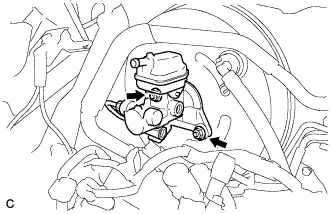
CONNECT BRAKE LINE
-
Using a union nut wrench (12 mm), connect the 2 brake lines to the brake master cylinder sub-assembly.
without union nut wrench 20 N*m 204 kgf*cm 15 ft.*lbf with union nut wrench 18 N*m 184 kgf*cm 13 ft.*lbf Note:
-
Use a torque wrench with a fulcrum length of 250 mm (9.84 in.).
-
This torque value is effective when the union nut wrench is parallel to the torque wrench.
-
-
- Click here
CONNECT NO. 1 RESERVOIR TUBE
-
Connect the No. 1 reservoir tube to the brake master cylinder reservoir assembly.
-
- Click here
INSTALL ENGINE ASSEMBLY WITH TRANSAXLE
- Click here
BLEED BRAKE SYSTEM
- Click here
INSPECT AND ADJUST BRAKE PEDAL