BRAKE BOOSTER (for RHD) REMOVAL
-
REMOVE ENGINE ASSEMBLY WITH TRANSAXLE
Tech Tips
Refer to the removal procedure of the engine assembly with transaxle Click here.
-
DRAIN BRAKE FLUID
-
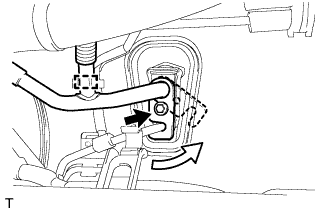
DISCONNECT NO. 1 RESERVOIR TUBE
-
Slide the clip and disconnect the No. 1 reservoir tube from the brake master reservoir assembly.
-
-
DISCONNECT BRAKE LINE
-
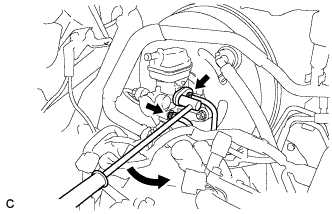
Using a union nut wrench (12 mm), disconnect the 2 brake lines from the brake master cylinder sub-assembly.
-
-
REMOVE BRAKE MASTER CYLINDER SUB-ASSEMBLY
-
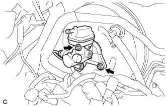
Remove the 2 nuts and brake master cylinder sub-assembly.
-
Remove the O-ring from the brake master cylinder sub-assembly.
Note
-
The master cylinder requires careful handling. Do not allow the master cylinder to receive any impact, such as from being dropped. Do not reuse a master cylinder that has been dropped.
-
Do not strike or pinch the master cylinder piston, and do not cause any damage to the master cylinder piston by any other means.
-
Make sure to release vacuum from the brake booster before removing the master cylinder from the brake booster.
-
When installing the master cylinder to the brake booster, or when removing the master cylinder from the brake booster, make sure that the master cylinder is kept horizontal or its tip faces downward (the piston faces upward) to prevent the master cylinder piston from falling out.
-
Do not allow any foreign objects to contaminate the master cylinder piston. If a foreign object gets on the piston, remove it by using a shop rag or a piece of cloth and then apply an even layer of lithium soap base glycol grease around the circumference (sliding part) of the piston.
-
Do not use any other type of grease or fluid.
-
-
-
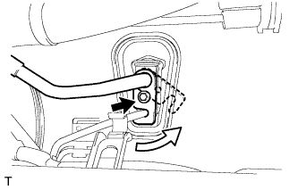
DISCONNECT VACUUM HOSE
-
Slide the clip and disconnect the vacuum hose.
-
-
REMOVE BRAKE VACUUM CHECK VALVE ASSEMBLY
-
Remove the vacuum check valve assembly from the brake booster assembly.
-
-
REMOVE CHECK VALVE GROMMET
-
Remove the check valve grommet from the brake booster assembly.
-
-
REMOVE BRAKE PEDAL RETURN SPRING
-
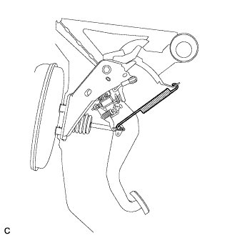
Remove the brake pedal return spring from the push rod pin and instrument panel reinforcement.
-
-
SEPARATE BRAKE MASTER CYLINDER PUSH ROD CLEVIS
-
Remove the clip and push rod pin, and separate the brake master cylinder push rod clevis from the brake pedal sub-assembly.
-
-
REMOVE NO. 1 COOLER REFRIGERANT SUCTION PIPE (w/o Rear Air Conditioning System)
-
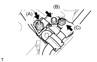
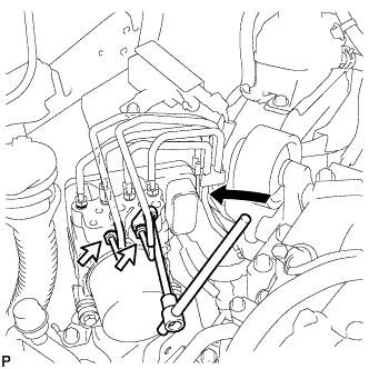
Remove the nut (A), and separate the discharge tube bracket from the suction hose bracket.
-
Remove the bolt (B), and separate the suction hose bracket from the body.
-
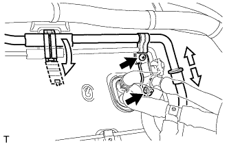
Remove the nut (C), and disconnect the suction hose sub-assembly from the No. 1 cooler refrigerant suction pipe.
-
Remove the bolt and slide the hook connector as shown in the illustration.
-
Separate the No. 1 cooler refrigerant suction pipe from the air conditioning unit.
-
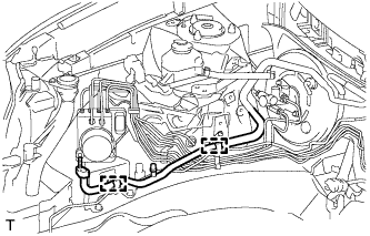
Disengage the 2 clamps and remove the No. 1 cooler refrigerant suction pipe.
Note
Seal the openings of the disconnected parts using vinyl tape to prevent moisture or foreign matter from entering.
-
-
REMOVE NO. 1 COOLER REFRIGERANT SUCTION PIPE (w/ Rear Air Conditioning System)
-
Remove the nut (A), and separate the discharge tube bracket from the suction hose bracket.
-
Remove the bolt (B), and separate the suction hose bracket from the body.
-
Remove the nut (C), and disconnect the suction hose sub-assembly from the No. 1 cooler refrigerant suction pipe.
-
Remove the bolt and slide the hook connector as shown in the illustration.
-
Disengage the clamp and separate the No. 1 cooler refrigerant suction pipe from the air conditioning unit.
-
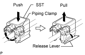
Disengage the piping clamp.
-
Install SST on the piping clamp.
- SST
- 09870-00015
Tech Tips
Confirm of the direction of the piping clamp claw and SST by checking the illustration shown on the caution label.
-
Push down SST and release the clamp lock.
Note
Be careful not to deform the tube when pushing SST.
-
Pull SST slightly and push the release lever, and then remove the piping clamp with SST.
-
Remove the piping clamp from SST.
-
-
Remove the nut and screw, disengage the clamp, and disconnect the No. 1 cooler refrigerant suction pipe from the cooler refrigerant suction pipe A by hand.
Note
Do not use a screwdriver or similar tool to disconnect the tube.
-
Disengage the 2 clamps and remove the No. 1 cooler refrigerant suction pipe.
Note
Seal the openings of the disconnected parts using vinyl tape to prevent moisture or foreign matter from entering.
-
-
REMOVE BRAKE BOOSTER ASSEMBLY
-
Using a union nut wrench (12 mm), disconnect the 2 brake lines from the brake actuator assembly.
-
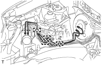
Disengage the 4 clamps and separate the 2 brake lines from the body.
Note
Be careful not to damage the brake lines or clamps. If any parts are damaged, replace them with new ones.
-
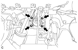
Remove the 4 nuts and brake booster assembly from the body.
Note
Do not damage the brake lines.
-
-
REMOVE BRAKE BOOSTER GASKET
-
Remove the brake booster gasket from the brake booster assembly.
-
-
REMOVE BRAKE MASTER CYLINDER PUSH ROD CLEVIS
-
Loosen the lock nut, and remove the brake master cylinder push rod clevis and lock nut from the brake booster assembly.
-