- Click here
INSTALL BRAKE BOOSTER GASKET
-
Install a new brake booster gasket to the brake booster assembly.
-
- Click here
INSTALL BRAKE BOOSTER ASSEMBLY
-
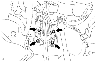
Install the brake booster assembly to the body and temporarily tighten the 4 nuts.
Note:Do not damage the brake lines.
Tip:Fully tighten the 4 nuts after installing the brake master cylinder push rod clevis and push rod clevis lock nut.
-
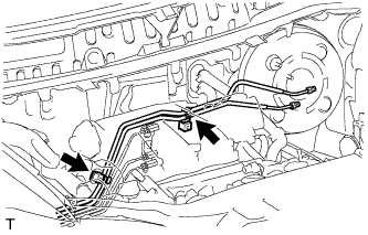
Engage the 2 clamps and install the 2 brake lines to the body.
Note:Be careful not to damage the brake lines or clamps. If any parts are damaged, replace them with new ones.
-
- Click here
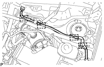
INSTALL ENGINE WIRE
-
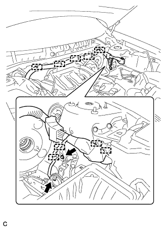
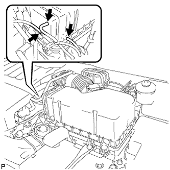
Engage the 9 clamps.
-
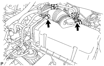
Connect the alarm horn connector and install the engine wire to the body with the bolt.
8.4 N*m 86 kgf*cm 74 in.*lbf
-
- Click here
INSTALL CHECK VALVE GROMMET
-
Install a new check valve grommet to the brake booster assembly.
-
- Click here
INSTALL BRAKE VACUUM CHECK VALVE ASSEMBLY
-
Install the vacuum check valve assembly to the brake booster assembly.
-
- Click here
CONNECT VACUUM HOSE
-
Connect the vacuum hose to the vacuum check valve and slide the clip.
-
- Click here
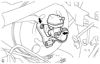
INSTALL BRAKE MASTER CYLINDER PUSH ROD CLEVIS
-
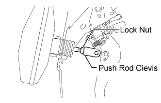
Install the push rod clevis lock nut and brake master cylinder push rod clevis to the brake booster assembly, and temporarily tighten the push rod clevis lock nut.
Note:Do not damage the brake lines.
Tip:Fully tighten the lock nut after adjusting the brake pedal height.
-
Fully tighten the 4 nuts to install the brake booster assembly to the body.
13 N*m 132 kgf*cm 10 ft.*lbf
-
- Click here
CONNECT BRAKE MASTER CYLINDER PUSH ROD CLEVIS
-
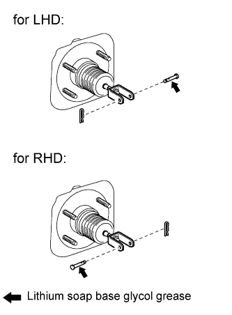
Apply lithium soap base glycol grease to the push rod pin.
-
Connect the brake master cylinder push rod clevis to the brake pedal with the push rod pin, and install a new clip as shown in the illustration.
-
- Click here
INSTALL BRAKE PEDAL RETURN SPRING
-
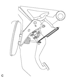
Install the brake pedal return spring between the instrument panel reinforcement and brake master cylinder push rod clevis.
-
- Click here
INSTALL BRAKE MASTER CYLINDER SUB-ASSEMBLY
-
Install a new O-ring to the brake master cylinder sub-assembly.
-
Install the brake master cylinder sub-assembly to the brake booster assembly with the 2 nuts.
13 N*m 132 kgf*cm 10 ft.*lbf Note:
-
The master cylinder requires careful handling. Do not allow the master cylinder to receive any impact, such as from being dropped. Do not reuse a master cylinder that has been dropped.
-
Do not strike or pinch the master cylinder piston, and do not cause any damage to the master cylinder piston by any other means.
-
When installing the master cylinder to the brake booster, or when removing the master cylinder from the brake booster, make sure that the master cylinder is kept horizontal or its tip faces downward (the piston faces upward) to prevent the master cylinder piston from falling out.
-
Do not allow any foreign objects to contaminate the master cylinder piston. If a foreign object gets on the piston, remove it by using a shop rag or a piece of cloth and then apply an even layer of lithium soap based glycol grease around the circumference (sliding part) of the piston.
-
Do not use any other type of grease or fluid.
-
-
- Click here
CONNECT BRAKE LINE
-
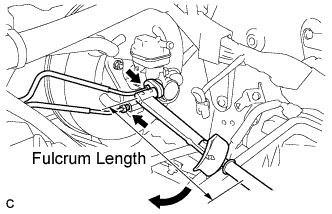
Using a union nut wrench (12 mm), connect the 2 brake lines to the brake master cylinder sub-assembly.
without union nut wrench 20 N*m 204 kgf*cm 15 ft.*lbf with union nut wrench 18 N*m 184 kgf*cm 13 ft.*lbf Note:
-
Use a torque wrench with a fulcrum length of 250 mm (9.84 in.).
-
This torque value is effective when the union nut wrench is parallel to the torque wrench.
-
-
- Click here
CONNECT NO. 1 RESERVOIR TUBE
-
Connect the No. 1 reservoir tube to the brake master cylinder reservoir assembly.
-
- Click here
BLEED BRAKE SYSTEM
- Click here
INSPECT AND ADJUST BRAKE PEDAL
- Click here
INSTALL CHARCOAL CANISTER ASSEMBLY
-
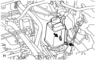
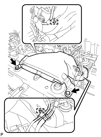
Install the charcoal canister assembly with the 2 bolts.
26.5 N*m 270 kgf*cm 20 ft.*lbf -
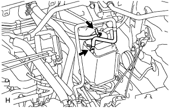
Connect the 2 hoses.
-
- Click here
INSTALL AIR CLEANER CASE SUB-ASSEMBLY
-
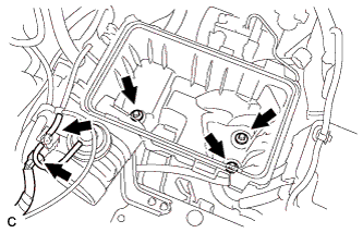
Install the air cleaner case with the 3 bolts.
5.0 N*m 51 kgf*cm 44 in.*lbf -
Connect the hose and connector.
-
- Click here
INSTALL AIR CLEANER FILTER ELEMENT SUB-ASSEMBLY
-
Install the air cleaner filter element sub-assembly.
-
- Click here
INSTALL AIR CLEANER CAP SUB-ASSEMBLY
-
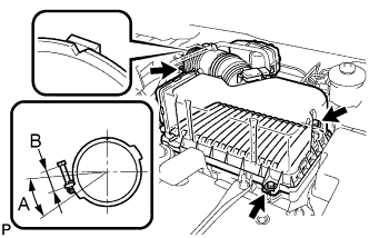
Install the air cleaner filter element, align the groove on the air cleaner hose with the throttle body alignment tab and tighten the clamp as shown in the illustration.
Tip:
-
A = 30°
-
B = 11 to 14 mm (0.433 in. to 0.551 in.)
-
-
Install the air cleaner cap with the 2 bolts and clips.
5.0 N*m 51 kgf*cm 44 in.*lbf -
Connect the 3 vacuum hoses.
-
Connect the mass air flow meter connector.
-
Connect the No. 2 ventilation hose and fuel vapor feed hose assembly.
-
- Click here
INSTALL NO. 2 AIR CLEANER INLET
-
Install the No. 2 air cleaner inlet with the 2 bolts.
7.0 N*m 71 kgf*cm 62 in.*lbf -
Connect the 2 vacuum hoses and harness clamps.
-
- Click here
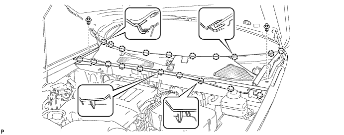
INSTALL COOL AIR INTAKE DUCT SEAL
-
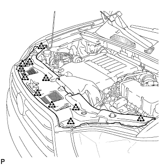
Install the cool air intake duct seal with the 11 clips.
-
- Click here
INSTALL OUTER COWL TOP PANEL SUB-ASSEMBLY
-
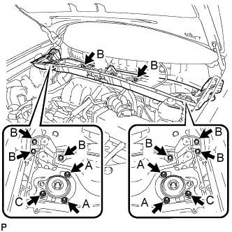
Install the outer cowl top panel sub-assembly with the 8 bolts and 6 nuts.
Nut A 85 N*m 866 kgf*cm 63 ft.*lbf Bolt B 8.8 N*m 90 kgf*cm 78 in.*lbf Nut C 8.8 N*m 90 kgf*cm 78 in.*lbf -
Engage the 4 clamps.
-
- Click here
INSTALL WINDSHIELD WIPER MOTOR AND LINK
-
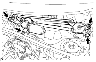
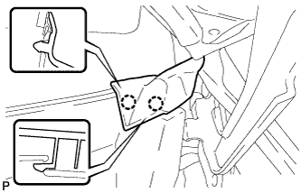
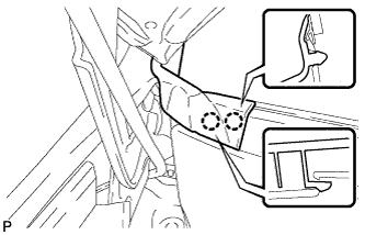
Install the windshield wiper motor and link assembly with the 4 bolts.
7.0 N*m 71 kgf*cm 62 in.*lbf -
Connect the connector.
-
- Click here
INSTALL COWL TOP VENTILATOR LOUVER SUB-ASSEMBLY
-
Engage the 20 claws.
-
Install the cowl top ventilator louver sub-assembly with the 2 clips.
-
Engage the 2 claws and connect the front fender to cowl side seal LH.
-
Engage the 2 claws and connect the front fender to cowl side seal RH.
-
- Click here
INSTALL FRONT WIPER ARM AND BLADE ASSEMBLY RH
-
Operate the wiper and stop the windshield wiper motor at the automatic stop position.
-
When reinstalling:
-
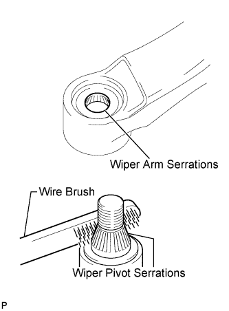
Clean the wiper arm serrations.
-
Clean the wiper pivot serrations with a wire brush.
-
-
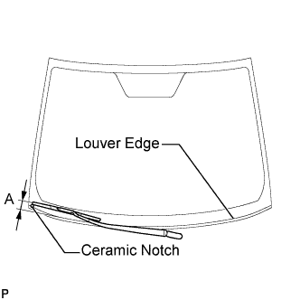
Install the front wiper arm and blade assembly RH with the nut to the position shown in the illustration.
24 N*m 245 kgf*cm 18 ft.*lbf Tip:Hold the wiper arm by hand when tightening the nut.
Area Measurement A 25.6 mm (1.00 in.)
-
- Click here
INSTALL FRONT WIPER ARM AND BLADE ASSEMBLY LH
-
Operate the wiper and stop the windshield wiper motor at the automatic stop position.
-
When reinstalling:
-
Clean the wiper arm serrations.
-
Clean the wiper pivot serrations with a wire brush.
-
-
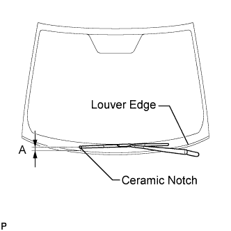
Install the front wiper arm and blade assembly LH with the nut to the position shown in the illustration.
24 N*m 245 kgf*cm 18 ft.*lbf Tip:Hold the wiper arm by hand when tightening the nut.
Area Measurement A 31.9 mm (1.26 in.) -
Operate the front wipers while spraying washer fluid onto the windshield glass. Make sure that the front wipers function properly and the wipers do not come into contact with the vehicle body.
-