YAW RATE AND ACCELERATION SENSOR INSTALLATION
-
INSTALL YAW RATE AND ACCELERATION SENSOR
-
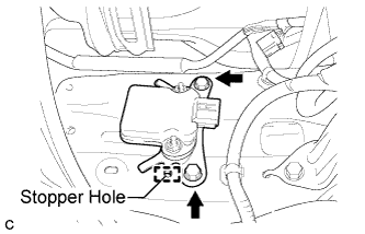
Install the yaw rate and acceleration sensor with the 2 bolts.
- Torque:
- 15 N*m { 153 kgf*cm, 11 ft.*lbf }
Note
-
Be sure to insert the yaw rate and acceleration sensor claw into the stopper hole while installing the yaw rate and acceleration sensor.
-
Do not damage the yaw rate and acceleration sensor.
-
Make sure that the yaw rate and acceleration sensor is installed securely.
-
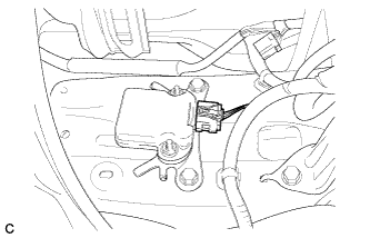
Connect the connector to the yaw rate and acceleration sensor.
Note
Make sure that the yaw rate and acceleration sensor connector is connected securely.
-
-
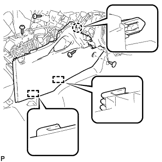
INSTALL FRONT NO. 1 CONSOLE BOX INSERT (for LHD)
-
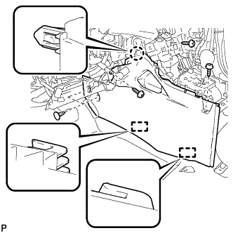
Engage the claw and 2 guides.
-
Install the front No. 1 console box insert with the 3 screws <F> and 2 clips.
-
-
INSTALL FRONT NO. 1 CONSOLE BOX INSERT (for RHD)
-
Engage the claw and 2 guides.
-
Install the front No. 1 console box insert with the 3 screws <F> and clip.
-
-
INSTALL FRONT NO. 2 CONSOLE BOX INSERT (for LHD)
-
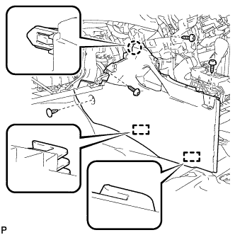
Engage the claw and 2 guides.
-
Install the front No. 2 console box insert with the 3 screws <F> and clip.
-
-
INSTALL FRONT NO. 2 CONSOLE BOX INSERT (for RHD)
-
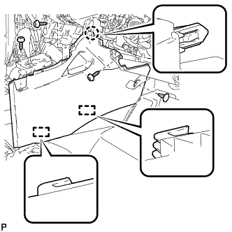
Engage the claw and 2 guides.
-
Install the front No. 2 console box insert with the 3 screws <F> and clip.
-
-
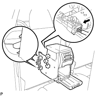
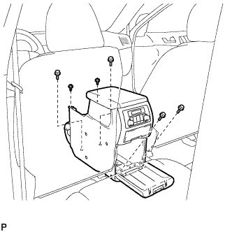
INSTALL CONSOLE BOX ASSEMBLY (w/o Rear Air Conditioning System)
-
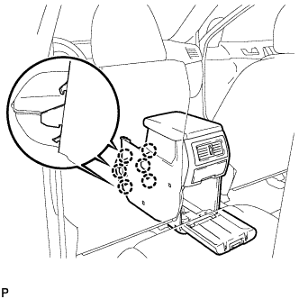
Engage the 6 claws.
-
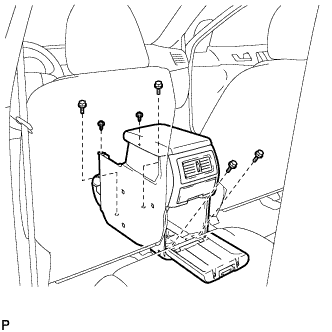
Install the console box assembly with the 4 bolts and 2 screws.
-
-
INSTALL CONSOLE BOX ASSEMBLY (w/ Rear Air Conditioning System)
-
Engage the 6 claws.
-
Connect the connector.
-
Install the console box assembly with the 4 bolts and 2 screws.
-
-
INSTALL LOWER REAR CONSOLE BOX
-
Install the lower rear console box.
-
-
INSTALL NO. 2 CONSOLE BOX DUCT (w/o Rear Air Conditioning System)
-
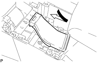
Install the No. 2 console box duct as shown in the illustration.
-
-
INSTALL UPPER CONSOLE PANEL SUB-ASSEMBLY
-
Connect the connector.
-
Engage the 4 claws and 4 clips, and install the upper console panel sub-assembly.
-
-
INSTALL LOWER INSTRUMENT PANEL SUB-ASSEMBLY
-
Connect each connector and clamp.
-
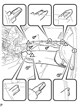
Engage the 4 claws and 3 clips.
-
Install the lower instrument panel sub-assembly with the 2 bolts <B> and 3 screws <F>.
-
-
INSTALL NO. 2 INSTRUMENT PANEL UNDER COVER SUB-ASSEMBLY
-
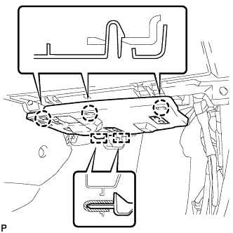
Engage the 2 guides.
-
Engage the 3 claws and install the No. 2 instrument panel under cover sub-assembly.
-
-
INSTALL COWL SIDE TRIM SUB-ASSEMBLY RH
Tech Tips
Use the same procedure for the RH side and the LH side.
-
INSTALL FRONT DOOR SCUFF PLATE RH
Tech Tips
Use the same procedure for the RH side and the LH side.
-
INSTALL LOWER INSTRUMENT PANEL FINISH PANEL SUB-ASSEMBLY (for Automatic Air Conditioning System)
-

Connect the hood lock control cable assembly.
-
Connect each connector and the aspirator duct.
-

Engage the 3 claws and 10 clips.
-
Install the lower instrument panel finish panel sub-assembly with the 2 bolts <B>.
-
-
INSTALL LOWER INSTRUMENT PANEL FINISH PANEL SUB-ASSEMBLY (for Manual Air Conditioning System)
-

Connect the hood lock control cable assembly.
-
Connect each connector.
-
Engage the 3 claws and 10 clips.
-
Install the lower instrument panel finish panel sub-assembly with the 2 bolts <B>.
-
-
INSTALL COWL SIDE TRIM SUB-ASSEMBLY LH
-

Engage the claw and clip, install the cowl side trim sub-assembly LH.
-
Install the clip.
-
-
INSTALL FRONT DOOR SCUFF PLATE LH
-

Engage the guide and the 8 claws, and install the front door scuff plate LH.
-
-
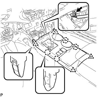
INSTALL CENTER INSTRUMENT CLUSTER FINISH PANEL ASSEMBLY (w/ Smart Entry and Start System)
-
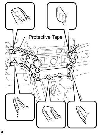
Apply protective tape to the areas shown in the illustration.
-
Connect each connector.
-
Engage the 10 claws and 8 clips, and install the center instrument cluster finish panel assembly.
Note
Do not the damage the instrument panel safety pad assembly and lower instrument panel finish panel sub-assembly.
-
-
INSTALL CENTER INSTRUMENT CLUSTER FINISH PANEL ASSEMBLY (w/o Smart Entry and Start System)
-

Apply protective tape to the areas shown in the illustration.
-
Connect each connector.
-
Engage the 10 claws and 8 clips, and install the center instrument cluster finish panel assembly.
Note
Do not the damage the instrument panel safety pad assembly and lower instrument panel finish panel sub-assembly.
-
-
CONNECT CABLE TO NEGATIVE BATTERY TERMINAL
Note
When disconnecting the cable, some systems need to be initialized after the cable is reconnected. Click here
-
PERFORM YAW RATE AND ACCELERATION SENSOR ZERO POINT CALIBRATION
-
CHECK FOR YAW RATE SENSOR SIGNAL