REAR SPEED SENSOR (for 4WD) INSTALLATION
Tech Tips
-
Use the same procedures for the LH side and RH side.
-
The following procedure is for the LH side.
-
If the sensor rotor needs to be replaced, replace it together with the outboard joint shaft assembly.
-
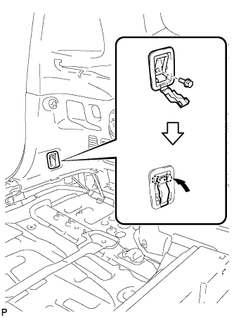
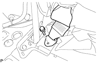
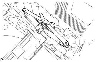
INSTALL REAR SPEED SENSOR
-
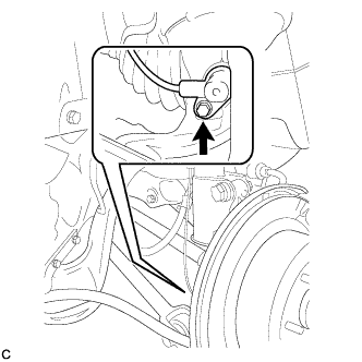
Install the rear speed sensor with the bolt.
- Torque:
- 8.0 N*m { 82 kgf*cm, 71 in.*lbf }
Note
-
Keep the rear speed sensor tip and sensor installation hole free from foreign matter.
-
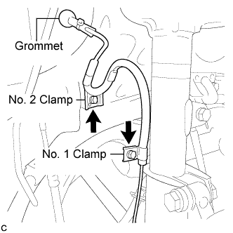
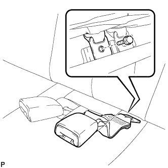
Install the No. 1 clamp and No. 2 clamp with the 2 bolts.
- Torque:
- 5.0 N*m { 51 kgf*cm, 44 in.*lbf }
Note
Do not twist the rear speed sensor wire when installing the clamp.
-
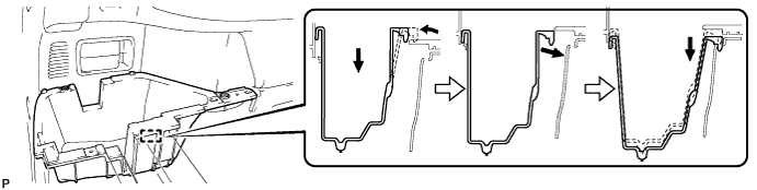
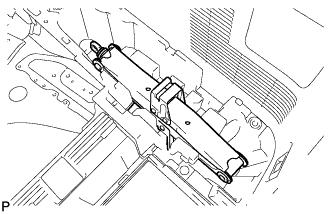
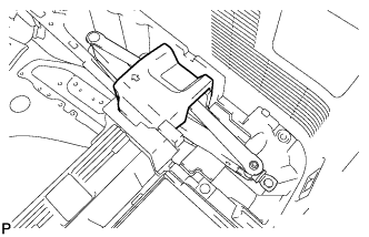
Insert the connector and grommet to the inside of the vehicle through the passage hole in the wheel well.
Note
Make sure the grommet's band clamp remains on the outside of the vehicle.
-
Hold the grommet and pull it from the inside of the vehicle to the outside of the vehicle. Then fix it in place so that it is not tilted.
Note
When pulling out the grommet, do not grip the sensor wire.
-
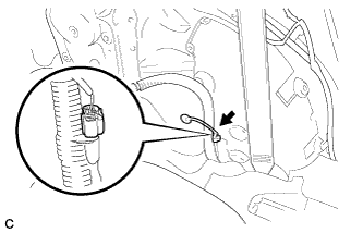
Connect the rear speed sensor connector.
-
-
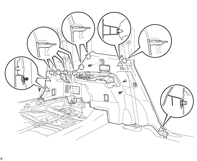
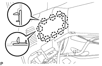
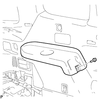
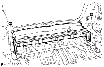
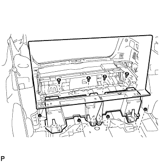
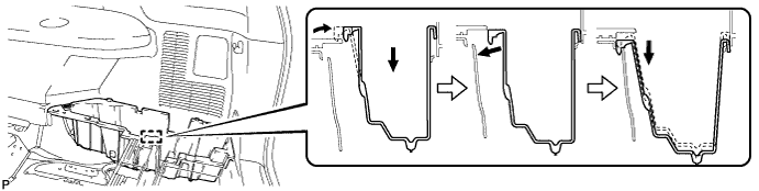
INSTALL DECK TRIM SIDE PANEL ASSEMBLY LH
-
Engage the 4 clips and the 7 claws.
-
Install the 2 clips.
-
Install the deck trim side panel assembly LH with the 2 bolts.
-
-
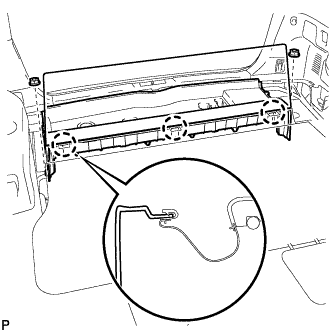
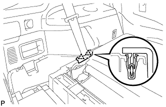
INSTALL REAR NO. 1 SEAT OUTER BELT ASSEMBLY LH
-
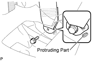
Connect the floor anchor end of the rear No. 1 seat outer belt assembly and install the bolt.
- Torque:
- 42 N*m { 428 kgf*cm, 31 ft.*lbf }
Note
Do not allow the anchor part of the rear No. 1 seat outer belt assembly to overlap the protruding part of the floor panel.
-
-
INSTALL FRONT DECK SIDE TRIM COVER LH
-
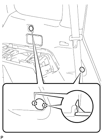
Engage the 4 claws and install the 2 front deck side trim covers LH.
-
-
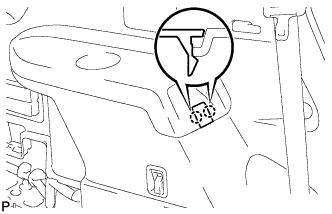
INSTALL NO. 2 DECK SIDE TRIM HOOK
-
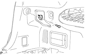
Install the No. 2 deck side trim hook with the screw.
-
-
INSTALL ROPE HOOK ASSEMBLY
-
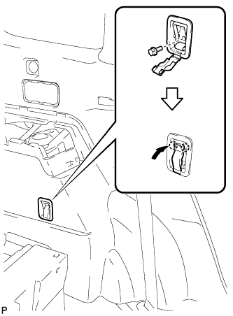
for Front Side:
-
Install the rope hook assembly with the bolt.
- Torque:
- 6.5 N*m { 66 kgf*cm, 58 in.*lbf }
-
Engage the 2 claws.
-
-
for Rear Side:
-
Install the rope hook assembly with the bolt.
- Torque:
- 6.5 N*m { 66 kgf*cm, 58 in.*lbf }
-
Engage the 2 claws.
-
-
-
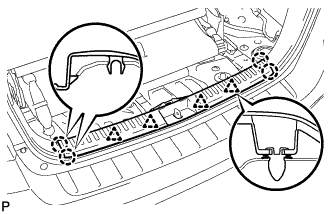
INSTALL REAR DECK TRIM COVER (w/o Remote Folding Function)
-
Engage the 10 claws and install the rear deck trim cover.
-
-
INSTALL RECLINING REMOTE CONTROL LEVER BEZEL LH (w/ Remote Folding Function)
-
Engage the 5 claws and install the reclining remote control bezel LH.
-
-
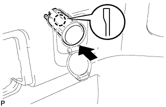
INSTALL REAR POWER OUTLET SOCKET COVER
-
Engage the 2 claws and install the rear power outlet socket cover.
-
-
INSTALL REAR POWER POINT SOCKET ASSEMBLY
-
Engage the claw and install the rear power point socket assembly.
-
Connect the connector.
-
-
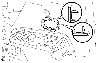
INSTALL REAR COMBINATION LIGHT SERVICE COVER LH
-
Engage the 2 guides and 6 claws, and install the rear combination light service cover LH.
-
-
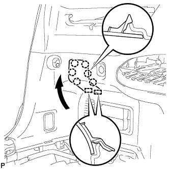
INSTALL SIDE TRIM COVER LH
-
Engage the 10 claws and install the side trim cover LH.
-
-
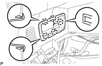
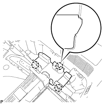
INSTALL DECK SIDE TRIM LH
-
Engage the 3 guides and 4 claws as shown in the illustration.
-
Install the deck side trim LH with the bolt.
-
-
INSTALL DECK SIDE TRIM COVER NO.2
-
Engage the 2 claws and install the deck side trim cover LH.
-
-
INSTALL REAR FLOOR FINISH PLATE
-
Engage the 4 clips and the 4 claws, and install the rear floor finish plate.
-
-
INSTALL REAR NO. 2 SEAT ASSEMBLY (w/ Rear No. 2 Seat)
-
Install the rear No. 2 seat assembly with the 4 bolts.
- Torque:
- 37 N*m { 377 kgf*cm, 27 ft.*lbf }
-
-
CONNECT REAR SEAT LAP TYPE BELT ASSEMBLY RH (w/ Rear No. 2 Seat)
-
Install the rear seat lap type belt assembly RH with the bolt.
- Torque:
- 42 N*m { 428 kgf*cm, 31 ft.*lbf }
Note
After installing the belt, check that it is not twisted.
-
-
CONNECT REAR SEAT LAP TYPE BELT ASSEMBLY LH (w/ Rear No. 2 Seat)
-
Install the rear seat lap type belt assembly LH with the bolt.
- Torque:
- 42 N*m { 428 kgf*cm, 31 ft.*lbf }
Note
After installing the belt, check that it is not twisted.
-
-
INSTALL REAR NO. 2 SEAT INNER BELT ASSEMBLY (w/ Rear No. 2 Seat)
-
Install the rear No. 2 seat inner belt assembly with the bolt.
- Torque:
- 42 N*m { 428 kgf*cm, 31 ft.*lbf }
Note
Do not allow the anchor part of the rear No. 2 seat inner belt assembly to overlap the protruding part of the rear No. 2 seat bracket.
Tech Tips
Use the same procedure for the RH side and LH side.
-
-
INSTALL REAR DECK FLOOR BOX (w/o Rear No. 2 Seat)
-
Install the rear deck floor box with the 2 nuts.
-
-
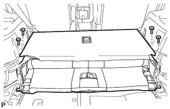
INSTALL DECK FLOOR BOARD ASSEMBLY (w/o Rear No. 2 Seat)
-
Install the 2 nuts and the deck floor board assembly.
-
Engage the 3 claws.
-
-
INSTALL REAR MAT
-
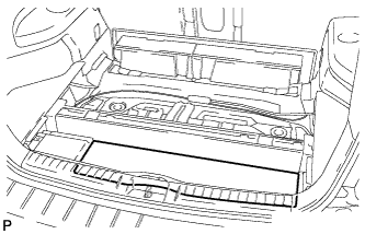
Install the rear mat.
-
-
INSTALL DECK FLOOR BOARD ASSEMBLY (w/ Rear No. 2 Seat)
-
Install the rear deck floor board assembly with the 4 nuts and 4 bolts.
-
-
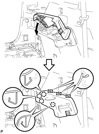
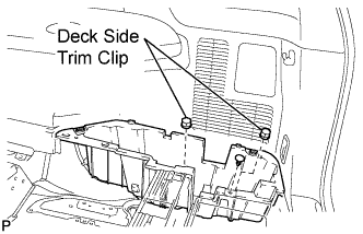
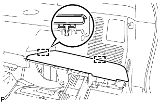
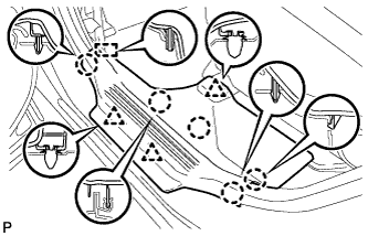
INSTALL DECK SIDE TRIM BOX LH
-
Install the deck side trim box LH as shown in the illustration.
-
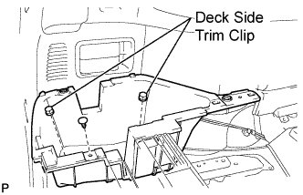
Install the 2 deck side trim clips and the clip.
-
-
INSTALL REAR SEAT SIDE COVER LH (w/ Rear No. 2 Seat)
-
Engage the 2 clips and install the rear seat side cover LH.
-
-
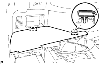
INSTALL DECK SIDE TRIM BOX RH
-
Install the deck side trim box RH as shown in the illustration.
-
Install the 2 deck side trim clips and the clip.
-
-
INSTALL JACK CARRIER ASSEMBLY (for LHD)
-

Engage the 3 claws, and install the jack carrier assembly.
-
-
INSTALL JACK CARRIER ASSEMBLY (for RHD)
-
Engage the 3 claws, and install the jack carrier assembly.
-
-
INSTALL JACK ASSEMBLY (for LHD)
-
Install the jack assembly.
-
-
INSTALL JACK ASSEMBLY (for RHD)
-
Install the jack assembly.
-
-
INSTALL JACK CARRIER CUSHION (for LHD)
-
Install the jack carrier cushion.
-
-
INSTALL JACK CARRIER CUSHION (for RHD)
-

Install the jack carrier cushion.
-
-
INSTALL JACK CARRIER SUPPORT
-
INSTALL REAR SEAT SIDE COVER RH (w/ Rear No. 2 Seat)
-
Engage the 2 clips and install the rear seat side cover RH.
-
-
INSTALL REAR NO. 1 FLOOR BOARD (w/o Rear No. 2 Seat)
-
Engage the 3 clips and install the rear floor board spacer to the No. 1 deck board.
-
-
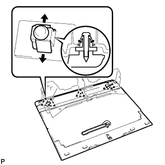
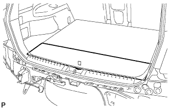
INSTALL TONNEAU COVER ASSEMBLY (w/ Tonneau Cover)
-
Install the tonneau cover assembly.
-
-
INSTALL NO. 2 DECK BOARD SUB-ASSEMBLY
-
Engage the 2 guides and install the No. 2 deck board sub-assembly.
-
-
INSTALL NO. 3 DECK BOARD SUB-ASSEMBLY
-
Engage the 2 guides and install the No. 3 deck board sub-assembly.
-
-
INSTALL DECK BOARD ASSEMBLY
-
Install the deck board sub-assembly.
-
-
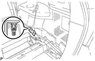
INSTALL REAR DOOR OPENING TRIM WEATHERSTRIP LH
-
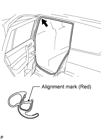
Align the alignment mark (red) on the weatherstrip with the protruding portion on the body indicated by the arrow in the illustration, and install the rear door opening trim weatherstrip LH.
Note
After installation, check that the corners fit correctly.
-
-
INSTALL REAR DOOR SCUFF PLATE LH
-
Engage the guide, 3 clips and 5 claws, and install the rear door scuff plate LH.
-
-
CONNECT CABLE TO NEGATIVE BATTERY TERMINAL
Note
When disconnecting the cable, some systems need to be initialized after the cable is reconnected. Click here
-
CHECK FOR REAR SPEED SENSOR SIGNAL
Tech Tips