-
Use the same procedures for the LH side and RH side.
-
The following procedure is for the LH side.
-
If the sensor rotor needs to be replaced, replace it together with the outboard joint shaft assembly.
- Click here
DISCONNECT CABLE FROM NEGATIVE BATTERY TERMINAL
Note:When disconnecting the cable, some systems need to be initialized after the cable is reconnected. (Click here)
- Click here
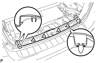
REMOVE REAR DOOR SCUFF PLATE LH
-
Disengage the 5 claws, 3 clips and guide, and remove the rear door scuff plate LH.
-
- Click here
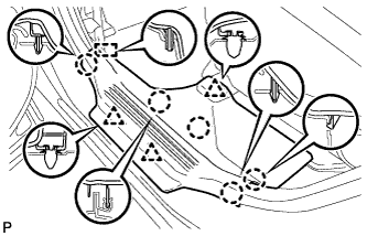
REMOVE REAR DOOR OPENING TRIM WEATHERSTRIP LH
-
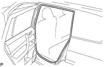
Remove the rear door opening trim weatherstrip LH.
-
- Click here
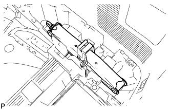
REMOVE DECK BOARD ASSEMBLY
-
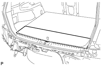
Remove the deck board assembly.
-
- Click here
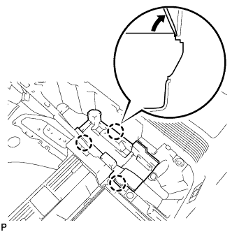
REMOVE NO. 3 DECK BOARD SUB-ASSEMBLY
-
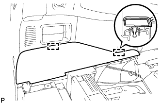
Disengage the 2 guides and remove the No. 3 deck board sub-assembly.
-
- Click here
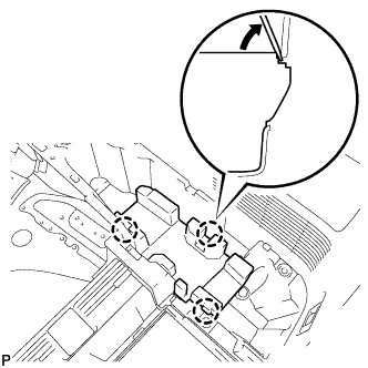
REMOVE NO. 2 DECK BOARD SUB-ASSEMBLY
-
Disengage the 2 guides and remove the No. 2 deck board sub-assembly.
-
- Click here
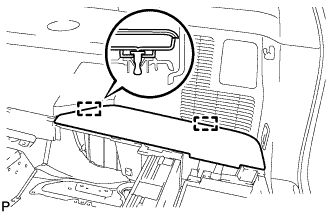
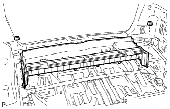
REMOVE TONNEAU COVER ASSEMBLY (w/ Tonneau Cover)
-
Remove the tonneau cover assembly.
-
- Click here
REMOVE TONNEAU COVER ASSEMBLY (w/ Tonneau Cover)
-
Remove the tonneau cover assembly.
-
- Click here
REMOVE REAR NO. 1 FLOOR BOARD (w/o Rear No. 2 Seat)
-
Disengage the 3 clips and the 3 guides, and remove the rear No. 1 floor board.
-
- Click here
REMOVE REAR SEAT SIDE COVER LH (w/ Rear No. 2 Seat)
-
Disengage the 2 clips and remove the rear seat side cover LH.
-
- Click here
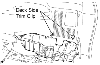
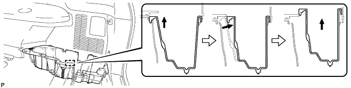
REMOVE DECK SIDE TRIM BOX LH
-
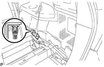
Remove the 2 deck side trim clips and clip.
-
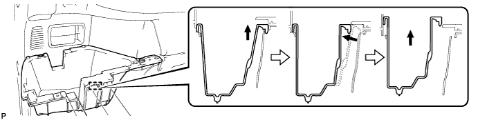
Remove the deck side trim box LH as shown in the illustration.
-
- Click here
REMOVE REAR SEAT SIDE COVER RH (w/ Rear No. 2 Seat)
-
Disengage the 2 clips and remove the rear seat side cover RH.
-
- Click here
REMOVE JACK CARRIER SUPPORT
- Click here
REMOVE JACK CARRIER CUSHION (for LHD)
-
Remove the jack carrier cushion.
-
- Click here
REMOVE JACK CARRIER CUSHION (for RHD)
-

Remove the jack carrier cushion.
-
- Click here
REMOVE JACK ASSEMBLY (for LHD)
-
Remove the jack assembly.
-
- Click here
REMOVE JACK ASSEMBLY (for RHD)
-
Remove the jack assembly.
-
- Click here
REMOVE JACK CARRIER ASSEMBLY (for LHD)
-
Using a screwdriver, disengage the 3 claws and remove the jack carrier assembly.
-
- Click here
REMOVE JACK CARRIER ASSEMBLY (for RHD)
-
Using a screwdriver, disengage the 3 claws and remove the jack carrier assembly.
-
- Click here
REMOVE DECK SIDE TRIM BOX RH
-
Remove the 2 deck side trim clips and clip.
-
Remove the deck side trim box RH as shown in the illustration.
-
- Click here
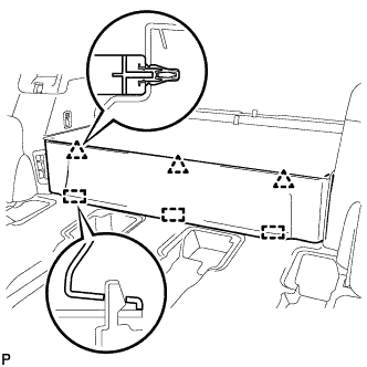
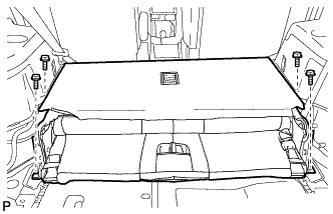
REMOVE DECK FLOOR BOARD ASSEMBLY (w/o Rear No. 2 Seat)
-
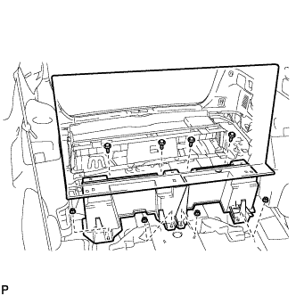
Remove the 4 bolts and 4 nuts.
-
Remove the deck floor board assembly.
-
- Click here
REMOVE REAR MAT
-
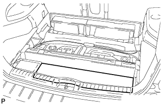
Remove the rear mat.
-
- Click here
REMOVE DECK FLOOR BOARD ASSEMBLY (w/ Rear No. 2 Seat)
-
Disengage the 3 claws.
-
Remove the 2 nuts and the deck floor board assembly.
-
- Click here
REMOVE REAR DECK FLOOR BOX (w/o Rear No. 2 Seat)
-
Remove the 2 nuts and the deck floor box.
-
- Click here
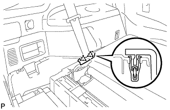
REMOVE REAR NO. 2 SEAT INNER BELT ASSEMBLY (w/ Rear No. 2 Seat)
-
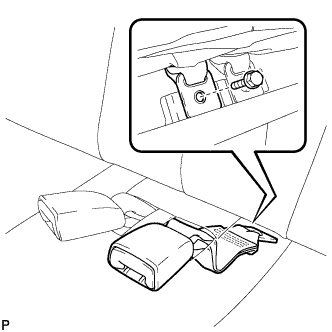
Remove the bolt and rear No. 2 seat inner belt assembly.
Tip:Use the same procedure for the RH side and LH side.
-
- Click here
DISCONNECT REAR SEAT LAP TYPE BELT ASSEMBLY LH (w/ Rear No. 2 Seat)
-
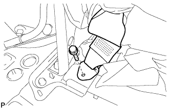
Remove the bolt and disconnect the rear seat lap type belt assembly LH.
-
- Click here
DISCONNECT REAR SEAT LAP TYPE BELT ASSEMBLY RH (w/ Rear No. 2 Seat)
Tip:Use the same procedure for the RH side and the LH side.
- Click here
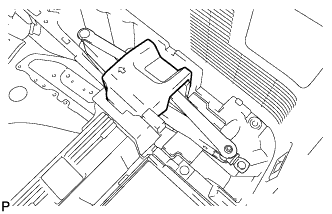
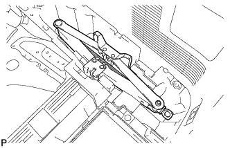
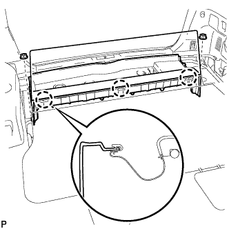
REMOVE REAR NO. 2 SEAT ASSEMBLY (w/ Rear No. 2 Seat)
-
Remove the 4 bolts and the rear No. 2 seat assembly.
-
- Click here
REMOVE REAR FLOOR FINISH PLATE
-
Disengage the 4 clips and the 4 claws, and remove the rear floor finish plate.
-
- Click here
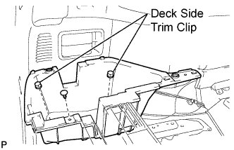
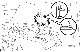
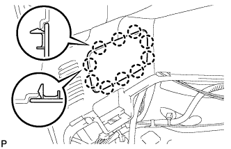
REMOVE DECK SIDE TRIM COVER NO.2
-
Using a screwdriver, disengage the 2 claws and remove the deck side trim cover LH.
Tip:Tape the screwdriver tip before use.
-
- Click here
REMOVE DECK SIDE TRIM LH
-
Remove the bolt.
-
Disengage the 4 claws and the 3 guides, and remove the deck side trim LH as shown in the illustration.
-
- Click here
REMOVE SIDE TRIM COVER LH
-
Disengage the 10 claws and remove the side trim cover LH.
-
- Click here
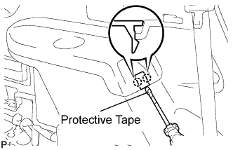
REMOVE REAR COMBINATION LIGHT SERVICE COVER LH
-

Using a screwdriver, disengage the 6 claws and 2 guides, and remove the rear combination light service cover LH.
Tip:Tape the screwdriver tip before use.
-
- Click here
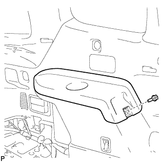
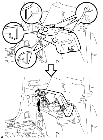
REMOVE REAR POWER POINT SOCKET ASSEMBLY
-
Disconnect the connector.
-
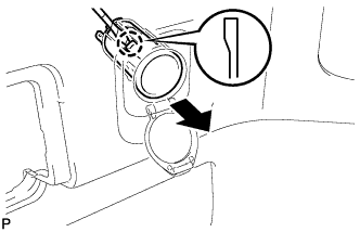
Disengage the claw and remove the rear power point socket assembly.
-
- Click here
REMOVE REAR POWER OUTLET SOCKET COVER
-
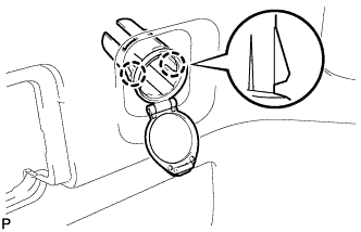
Disengage the 2 claws and remove the rear power outlet socket cover.
-
- Click here
REMOVE REAR DECK TRIM COVER (w/o Remote Folding Function)
-
Disengage the 10 claws and remove the rear deck trim cover.
-
- Click here
REMOVE RECLINING REMOTE CONTROL LEVER BEZEL LH (w/ Remote Folding Function)
-
Disengage the 5 claws and remove the reclining remote control bezel LH.
-
- Click here
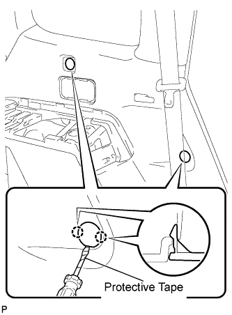
REMOVE ROPE HOOK ASSEMBLY (for LH Side)
-
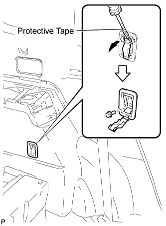
for Front Side:
-
Using a screwdriver, disengage the 2 claws.
Tip:Tape the screwdriver tip before use.
-
Remove the bolt and the rope hook assembly.
-
-
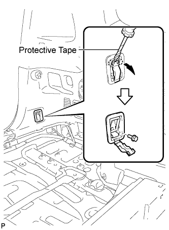
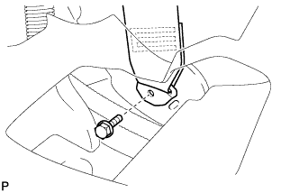
for Rear Side:
-
Using a screwdriver, disengage the 2 claws.
Tip:Tape the screwdriver tip before use.
-
Remove the bolt and rope hook assembly.
-
-
- Click here
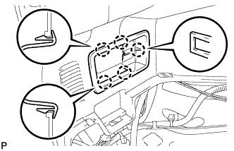
REMOVE NO. 2 DECK SIDE TRIM HOOK
-
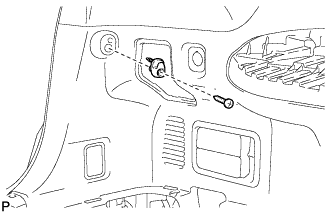
Remove the screw and the No. 2 deck side trim hook.
-
- Click here
REMOVE FRONT DECK SIDE TRIM COVER LH
-
Using a screwdriver, disengage the 4 claws and remove the 2 front deck side trim covers LH.
Tip:Tape the screwdriver tip before use.
-
- Click here
REMOVE REAR NO. 1 SEAT OUTER BELT ASSEMBLY LH
-
Remove the bolt and disconnect the floor end of the rear No. 1 seat outer belt assembly.
-
- Click here
REMOVE DECK TRIM SIDE PANEL ASSEMBLY LH
-
Remove the 2 bolts.
-
Remove the 2 clips.
-
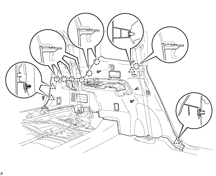
Disengage the 7 claws and 4 clips, and remove the deck trim side panel assembly LH.
-
- Click here
REMOVE REAR WHEEL
- Click here
REMOVE REAR SPEED SENSOR
-
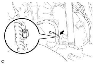
Disconnect the rear speed sensor connector.
-
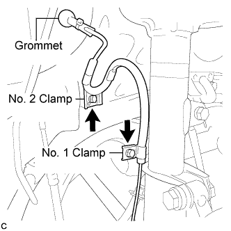
Disconnect the grommet of the rear speed sensor wire from the hole of the wheel house.
-
Remove the 2 bolts, No. 1 clamp and No. 2 clamp from the body and absorber.
-
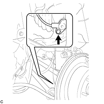
Remove the bolt and rear speed sensor body from the carrier.
Note:Keep the sensor tip and rear speed sensor installation hole free from foreign matter.
-