REAR SPEED SENSOR (for 2WD) INSTALLATION
Tech Tips
If the sensor rotor needs to be replaced, replace it together with the rear axle hub and bearing assembly with rear speed sensor.
-
INSTALL REAR SPEED SENSOR
-
Clean the contact surface between the rear axle hub and bearing assembly and a new rear speed sensor.
Note
Prevent foreign matter from attaching to the sensor rotor.
-
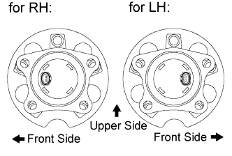
Place the rear speed sensor on the axle hub so that the connector is positioned as shown in the illustration.
-
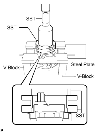
Using SST, a steel plates, V-blocks and press, install a new rear speed sensor to the rear axle hub and bearing assembly.
- SST
- 09214-76011
- 09213-58013
Note
-
Keep the rear speed sensor away from magnets.
-
Do not use a hammer to install the rear speed sensor.
-
Check that there is no foreign matter such as iron chips on the detecting portion of the rear speed sensor.
-
Slowly press in the rear speed sensor straight.
-
-
INSTALL REAR AXLE HUB AND BEARING ASSEMBLY WITH REAR SPEED SENSOR
-
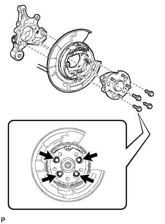
Install the parking brake assembly and the rear axle hub and bearing assembly with the 4 bolts.
- Torque:
- 75 N*m { 764 kgf*cm, 55 ft.*lbf }
Note
Do not twist the No. 3 parking brake cable assembly when installing it.
-
-
INSPECT REAR AXLE HUB BEARING LOOSENESS
-
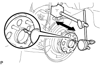
Using a dial indicator, check for looseness near the center of the axle hub.
Maximum looseness 0 mm (0 in.) Note
Ensure that the dial indicator is set perpendicular to the measurement surface.
If the looseness exceeds the maximum, replace the rear axle hub and bearing assembly.
-
-
INSPECT REAR AXLE HUB RUNOUT
-
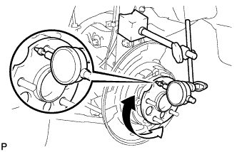
Using a dial indicator, check for runout on the surface of the axle hub outside the hub bolt.
Maximum runout 0.08 mm (0.0031 in.) Note
Ensure that the dial indicator is set perpendicular to the measurement surface.
If the runout exceeds the maximum, replace the rear axle hub and bearing assembly.
-
-
INSTALL REAR DISC
-
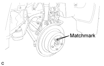
Align matchmarks and install the rear disc.
Note
When replacing the rear disc with a new one, select the installation position where the rear disc has minimal runout.
-
-
INSTALL REAR DISC BRAKE CALIPER ASSEMBLY
-
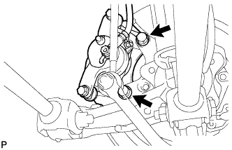
Install the rear disc brake caliper assembly with the 2 bolts.
- Torque:
- 78 N*m { 795 kgf*cm, 57 ft.*lbf }
-
-
INSTALL REAR SPEED SENSOR WIRE
-
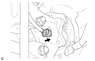
Connect the connector to the rear speed sensor.
-
-
INSTALL REAR WHEEL
- Torque:
- 103 N*m { 1050 kgf*cm, 76 ft.*lbf }
-
CONNECT CABLE TO NEGATIVE BATTERY TERMINAL
Note
When disconnecting the cable, some systems need to be initialized after the cable is reconnected. Click here
-
INSPECT AND ADJUST REAR WHEEL ALIGNMENT
Tech Tips
-
CHECK FOR REAR SPEED SENSOR SIGNAL
Tech Tips