FRONT SPEED SENSOR REMOVAL
Tech Tips
-
Use the same procedures for the LH side and RH side.
-
The following procedures is for the LH side.
-
If the sensor rotor needs to be replaced, replace it together with the front drive outboard joint shaft assembly.
-
DISCONNECT CABLE FROM NEGATIVE BATTERY TERMINAL
Note
When disconnecting the cable, some systems need to be initialized after the cable is reconnected. Click here
-
REMOVE FRONT WHEEL
-
REMOVE NO. 1 ENGINE UNDER COVER
-
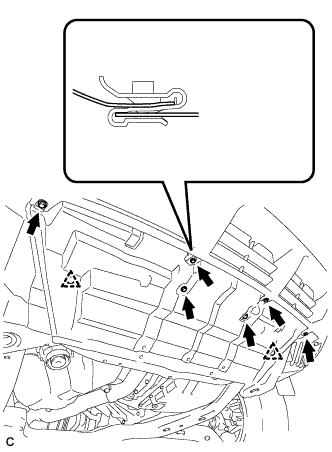
Remove the 6 bolts, 2 clips and No. 1 engine under cover.
-
-
REMOVE FRONT FENDER MOULDING SUB-ASSEMBLY LH
-
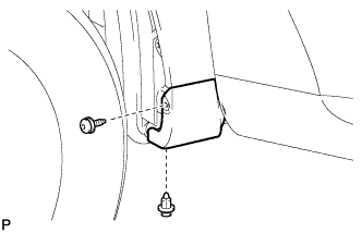
Remove the clip.
-
Using a 4 mm hexagon wrench, remove the screw.
-
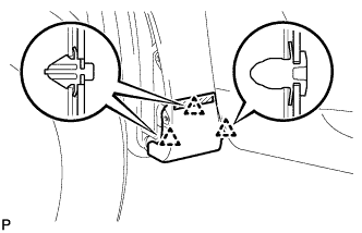
Peel off the front fender side protector and disengage the 3 clips, and then remove the front fender moulding sub-assembly.
-
Remove the pad from the front fender moulding sub-assembly.
-
Remove the 2 No. 4 clips from the front fender moulding sub-assembly.
-
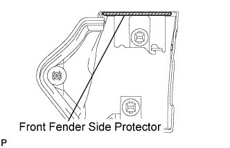
Remove the front fender side protector from the front fender moulding sub-assembly.
-
-
REMOVE FRONT WHEEL OPENING EXTENSION PAD
-
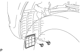
Remove the 2 screws and front wheel opening extension pad.
-
-
REMOVE FRONT FENDER LINER
-
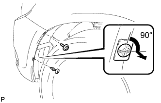
Remove the screw.
-
Using a screwdriver, turn the pin 90 degrees and remove the pin hold clip.
-
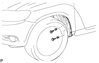
Using a 4 mm hexagon wrench, remove the 2 screws.
-
Remove the 2 grommets.
Tech Tips
The grommets need to be replaced with new ones because they will break when they are removed.
-
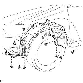
Remove the 5 clips, 8 screws and front fender liner LH.
-
-
REMOVE FRONT SPEED SENSOR
-
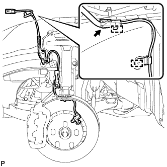
Disconnect the front speed sensor connector and remove the 2 clamps.
-
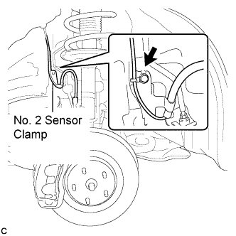
Remove the bolt and No. 2 sensor clamp from the body.
-
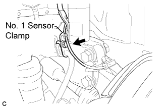
Remove the bolt, No. 1 sensor clamp, and flexible hose together from the shock absorber assembly.
-
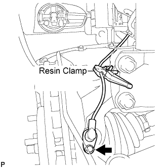
Remove the bolt, resin clamp, and the front speed sensor.
Note
-
Prevent foreign matter from attaching to the front speed sensor tip.
-
Clean the installation hole and the connect surface for the front speed sensor every time it is removed.
-
-