BRAKE ACTUATOR INSTALLATION
-
INSTALL BRAKE ACTUATOR
-
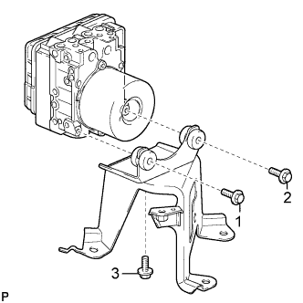
Install the brake actuator to the brake actuator bracket assembly with the 3 bolts.
- Torque:
- 5.4 N*m { 55 kgf*cm, 48 in.*lbf }
Note
-
Do not remove the hole plugs of a new brake actuator before connecting the 6 brake lines because the brake actuator is filled with brake fluid.
-
Do not hold with the actuator by the connector.
-
Tighten the 3 bolts in order the from shown in the illustration.
-
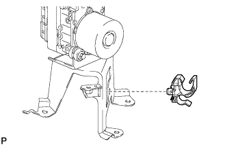
Install the piping clamp to the brake actuator bracket assembly.
-
-
INSTALL BRAKE ACTUATOR WITH BRACKET (for LHD)
-
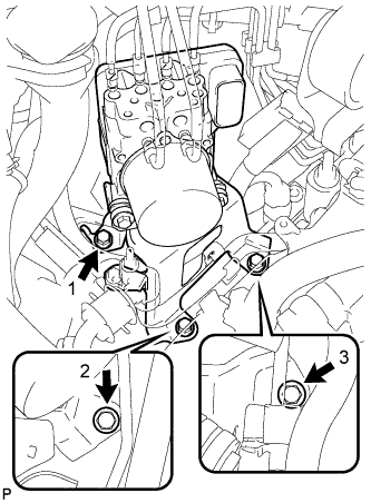
Install the brake actuator with bracket to the body with the 3 bolts.
- Torque:
- 19 N*m { 194 kgf*cm, 14 ft.*lbf }
Note
-
Do not damage the brake lines or wire harness.
-
Tighten the 3 bolts in order the from shown in the illustration.
-
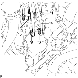
Temporarily tighten each brake line to the correct positions of the brake actuator with bracket as shown in the illustration.
Tech Tips
-
*1: To front wheel cylinder RH
-
*2: To front wheel cylinder LH
-
*3: To rear wheel cylinder RH
-
*4: To rear wheel cylinder LH
-
*5: From 1st of master cylinder
-
*6: From 2nd of master cylinder
-
-
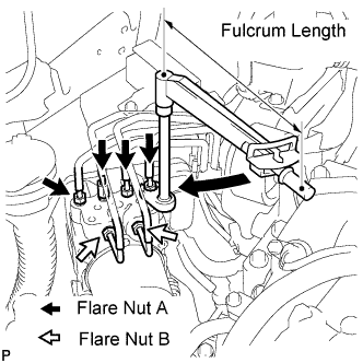
Using a union nut wrench (10 mm and 12 mm), fully tighten each brake line.
- Torque:
- Flare Nut A (M10) without union nut wrench
- 15 N*m { 155 kgf*cm, 11 ft.*lbf }
- Flare Nut A (M10) with union nut wrench
- 14 N*m { 143 kgf*cm, 10 ft.*lbf }
- Flare Nut B (M12) without union nut wrench
- 20 N*m { 204 kgf*cm, 15 ft.*lbf }
- Flare Nut B (M12) with union nut wrench
- 18 N*m { 184 kgf*cm, 13 ft.*lbf }
Note
-
Use a torque wrench with a fulcrum length of 250 mm (9.84 in.).
-
This torque value is effective when the union nut wrench is parallel to the torque wrench.
-
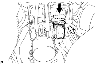
Connect the brake actuator connector.
Note
-
Make sure that the connector is locked securely.
-
Make sure that the actuator connector can be connected smoothly. Do not allow water, oil or dirt to enter.
-
-
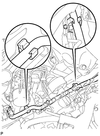
Install the No. 1 cooler refrigerant suction tube to the 2 clamps.
-

Install the suction hose bracket to the brake actuator bracket assembly with the nut and bolt.
- Torque:
- 9.8 N*m { 100 kgf*cm, 87 in.*lbf }
-
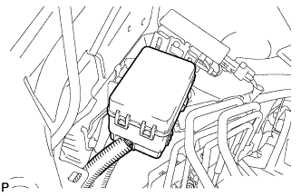
Install the relay box.
-
-
INSTALL BRAKE ACTUATOR WITH BRACKET (for RHD)
-
Install the brake actuator with bracket to the body with the 3 bolts.
- Torque:
- 19 N*m { 194 kgf*cm, 14 ft.*lbf }
Note
-
Do not damage the brake lines or wire harness.
-
Tighten the 3 bolts in order the from shown in the illustration.
-
Temporarily tighten each brake line to the correct position of the brake actuator with bracket as shown in the illustration.
Tech Tips
-
*1: To front wheel cylinder RH
-
*2: To front wheel cylinder LH
-
*3: To rear wheel cylinder RH
-
*4: To rear wheel cylinder LH
-
*5: From 1st of master cylinder
-
*6: From 2nd of master cylinder
-
-
Using a union nut wrench (10 mm and 12 mm), fully tighten each brake line.
- Torque:
- Flare Nut A (M10) without union nut wrench
- 15 N*m { 155 kgf*cm, 11 ft.*lbf }
- Flare Nut A (M10) with union nut wrench
- 14 N*m { 143 kgf*cm, 10 ft.*lbf }
- Flare Nut B (M12) without union nut wrench
- 20 N*m { 204 kgf*cm, 15 ft.*lbf }
- Flare Nut B (M12) with union nut wrench
- 18 N*m { 184 kgf*cm, 13 ft.*lbf }
Note
-
Use a torque wrench with a fulcrum length of 250 mm (9.84 in.).
-
This torque value is effective when the union nut wrench is parallel to the torque wrench.
-
Connect the brake actuator connector.
Note
-
Make sure that the connector is locked securely.
-
Make sure that the actuator connector can be connected smoothly. Do not allow water, oil or dirt to enter.
-
-
Install the No. 1 cooler refrigerant suction tube to the 2 clamps.
-
Install the suction hose bracket to the brake actuator bracket assembly with the nut and bolt.
- Torque:
- 9.8 N*m { 100 kgf*cm, 87 in.*lbf }
-
-
BLEED BRAKE SYSTEM
-
INSTALL V-BANK COVER SUB-ASSEMBLY
-
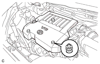
Fit the 3 retainers and install the V-bank cover.
-
-
CONNECT CABLE TO NEGATIVE BATTERY TERMINAL
Note
When disconnecting the cable, some systems need to be initialized after the cable is reconnected Click here.
-
INSPECT BRAKE ACTUATOR WITH INTELLIGENT TESTER
-
PERFORM YAW RATE AND ACCELERATION SENSOR ZERO POINT CALIBRATION
-
CHECK AND CLEAR DTCS