BRAKE ACTUATOR INSTALLATION
-
INSTALL BRAKE ACTUATOR
-
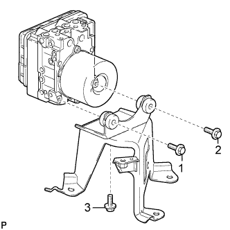
Install the brake actuator to the brake actuator bracket assembly with the 3 bolts.
- Torque:
- 5.4 N*m { 55 kgf*cm, 48 in.*lbf }
Note
-
Do not remove the hole plugs of a new brake actuator before connecting the 6 brake lines because the brake actuator is filled with brake fluid.
-
Do not hold with the actuator by the connector.
-
Tighten the 3 bolts in order the from shown in the illustration.
-
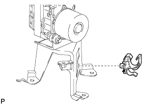
Install the piping clamp to the brake actuator bracket assembly.
-
-
INSTALL BRAKE ACTUATOR WITH BRACKET (for LHD)
-
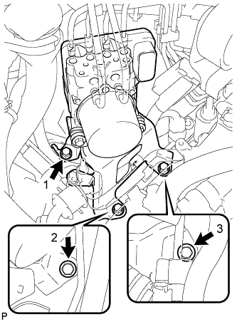
Install the brake actuator with bracket to the body with the 3 bolts.
- Torque:
- 19 N*m { 194 kgf*cm, 14 ft.*lbf }
Note
-
Do not damage the brake lines or wire harness.
-
Tighten the 3 bolts in order the from shown in the illustration.
-
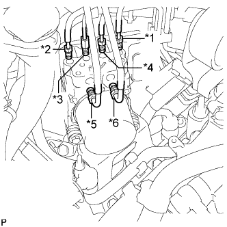
Temporarily tighten each brake line to the correct positions of the brake actuator with bracket as shown in the illustration.
Tech Tips
-
*1: To front wheel cylinder RH
-
*2: To front wheel cylinder LH
-
*3: To rear wheel cylinder RH
-
*4: To rear wheel cylinder LH
-
*5: From 1st of master cylinder
-
*6: From 2nd of master cylinder
-
-
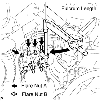
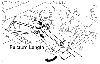
Using a union nut wrench (10 mm and 12 mm), fully tighten each brake line.
- Torque:
- Flare Nut A (M10) without union nut wrench
- 15 N*m { 155 kgf*cm, 11 ft.*lbf }
- Flare Nut A (M10) with union nut wrench
- 14 N*m { 143 kgf*cm, 10 ft.*lbf }
- Flare Nut B (M12) without union nut wrench
- 20 N*m { 204 kgf*cm, 15 ft.*lbf }
- Flare Nut B (M12) with union nut wrench
- 18 N*m { 184 kgf*cm, 13 ft.*lbf }
Note
-
Use a torque wrench with a fulcrum length of 250 mm (9.84 in.).
-
This torque value is effective when the union nut wrench is parallel to the torque wrench.
-
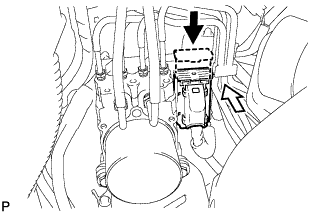
Connect the brake actuator connector.
Note
-
Make sure that the connector is locked securely.
-
Make sure that the actuator connector can be connected smoothly. Do not allow water, oil or dirt to enter.
-
-
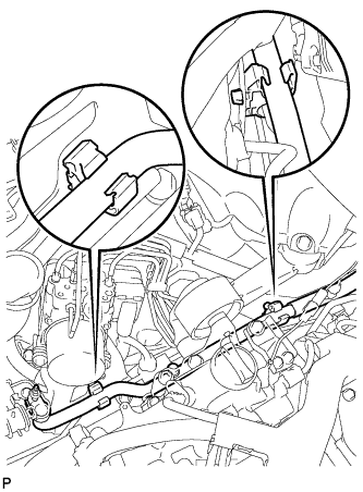
Install the No. 1 cooler refrigerant suction tube to the 2 clamps.
-

Install the suction hose bracket to the brake actuator bracket assembly with the nut and bolt.
- Torque:
- 9.8 N*m { 100 kgf*cm, 87 in.*lbf }
-
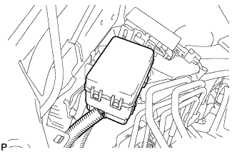
Install the relay box.
-
-
INSTALL BRAKE ACTUATOR WITH BRACKET (for RHD)
-
Install the brake actuator with bracket to the body with the 3 bolts.
- Torque:
- 19 N*m { 194 kgf*cm, 14 ft.*lbf }
Note
-
Do not damage the brake lines or wire harness.
-
Tighten the 3 bolts in order the from shown in the illustration.
-
Temporarily tighten each brake line to the correct position of the brake actuator with bracket as shown in the illustration.
Tech Tips
-
*1: To front wheel cylinder RH
-
*2: To front wheel cylinder LH
-
*3: To rear wheel cylinder RH
-
*4: To rear wheel cylinder LH
-
*5: From 1st of master cylinder
-
*6: From 2nd of master cylinder
-
-
Using a union nut wrench (10 mm and 12 mm), fully tighten each brake line.
- Torque:
- Flare Nut A (M10) without union nut wrench
- 15 N*m { 155 kgf*cm, 11 ft.*lbf }
- Flare Nut A (M10) with union nut wrench
- 14 N*m { 143 kgf*cm, 10 ft.*lbf }
- Flare Nut B (M12) without union nut wrench
- 20 N*m { 204 kgf*cm, 15 ft.*lbf }
- Flare Nut B (M12) with union nut wrench
- 18 N*m { 184 kgf*cm, 13 ft.*lbf }
Note
-
Use a torque wrench with a fulcrum length of 250 mm (9.84 in.).
-
This torque value is effective when the union nut wrench is parallel to the torque wrench.
-
Connect the brake actuator connector.
Note
-
Make sure that the connector is locked securely.
-
Make sure that the actuator connector can be connected smoothly. Do not allow water, oil or dirt to enter.
-
-
Install the No. 1 cooler refrigerant suction tube to the 2 clamps.
-
Install the suction hose bracket to the brake actuator bracket assembly with the nut and bolt.
- Torque:
- 9.8 N*m { 100 kgf*cm, 87 in.*lbf }
-
-
FILL RESERVOIR WITH BRAKE FLUID
-
Fill the reservoir with brake fluid.
Brake Fluid SAE J1703 or FMVSS No. 116 DOT 3 Note
Make sure that there is sufficient brake fluid in the reservoir.
-
-
BLEED BRAKE MASTER CYLINDER
Note
-
If the master cylinder is reinstalled or if the reservoir becomes empty, bleed the master cylinder.
-
To prevent brake fluid from adhering, cover the painted surfaces with a shop rag or a piece of cloth.
-
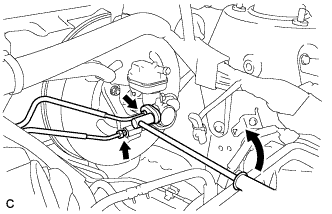
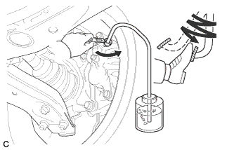
Using a union nut wrench (12 mm), disconnect the 2 brake lines from the master cylinder.
-
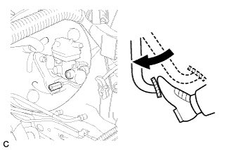
Slowly depress the brake pedal and hold it (*1).
-
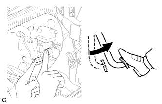
Cover the 2 outer holes with fingers, and release the brake pedal (*2).
-
Repeat (*1) and (*2) 3 or 4 times.
-
Using a union nut wrench (12 mm), connect the 2 brake lines to the master cylinder.
- Torque:
- w/o union nut wrench
- 20 N*m { 204 kgf*cm, 15 ft.*lbf }
- w/ union nut wrench
- 18 N*m { 184 kgf*cm, 13 ft.*lbf }
Note
-
Use a torque wrench with a fulcrum length of 250 mm (9.84 in.).
-
This torque value is effective when the union nut wrench is parallel to the torque wrench.
-
-
BLEED BRAKE LINE
Note
-
Bleed the brake line of the wheel farthest from the master cylinder first.
-
Add brake fluid to keep the level between the MIN and MAX lines of the reservoir while bleeding the brakes.
-
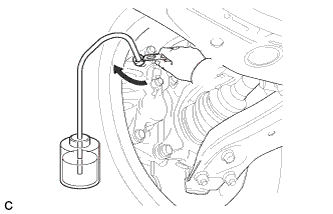
Connect a vinyl tube to the bleeder plug.
-
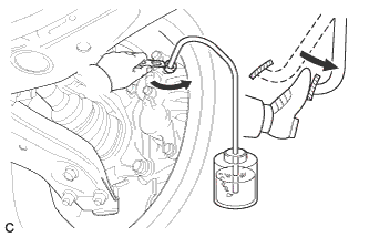
Depress the brake pedal several times, and then loosen the bleeder plug with the pedal depressed (*3).
-
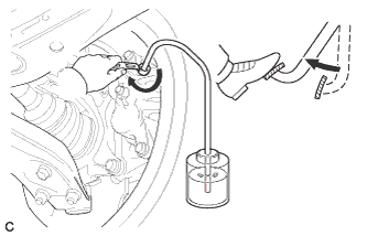
When fluid stops coming out, tighten the bleeder plug, and then release the brake pedal (*4).
-
Repeat (*3) and (*4) until all the air in the fluid is completely bled out.
-
Tighten the bleeder plug completely.
- Torque:
- 8.3 N*m { 85 kgf*cm, 73 in.*lbf }
-
Repeat the above procedure for each wheel to bleed the brake line.
-
-
BLEED BRAKE ACTUATOR
Note
After bleeding the brake system, if the specified height or feel of the brake pedal cannot be obtained, bleed the brake actuator assembly with the intelligent tester by following the procedure below.
-
Depress the brake pedal more than 20 times with the ignition switch off.
-
Connect the intelligent tester to the DLC3, and then turn the ignition switch on (IG).
Note
Do not start the engine.
-
Turn the intelligent tester on and select "AIR BLEEDING" on the screen.
Note
-
Refer to the intelligent tester operator's manual for further details.
-
Bleed the air by following the steps displayed on the intelligent tester.
-
-
Bleed the air according to "Step 1: Increase" on the intelligent tester display.
Note
-
Make sure that the master cylinder reservoir tank does not run out of brake fluid.
-
Add brake fluid to keep the level between the MIN and MAX lines of the reservoir while bleeding the brakes.
-
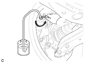
Connect a vinyl tube to either one of the bleeder plugs.
-
Depress the brake pedal several times, and then loosen the bleeder plug connected to the vinyl tube with the pedal depressed (*5).
-
When fluid stops coming out, tighten the bleeder plug, and then release the brake pedal (*6).
-
Repeat (*5) and (*6) until all the air in the fluid is completely bled out.
-
Tighten the bleeder plug completely.
- Torque:
- 8.3 N*m { 85 kgf*cm, 73 in.*lbf }
-
Repeat the above procedure for the rest of the wheels to bleed the brake lines.
-
-
Bleed the suction line according to "Step 2: Inhalation" on the intelligent tester display.
Note
-
Bleed the suction line by following the steps displayed on the intelligent tester.
-
Add brake fluid to keep the level between the MIN and MAX lines of the reservoir while bleeding the brakes.
-
Connect a vinyl tube to the bleeder plug at the right front wheel or the right rear wheel and loosen the bleeder plug.
-
Operate the brake actuator assembly to bleed the air using the intelligent tester (*7).
Note
-
During this step, be sure to release the brake pedal.
-
The actuator operation stops automatically in 4 seconds.
-
-
Check that the actuator operation has stopped by referring to the intelligent tester display, and tighten the bleeder plug (*8).
-
Repeat (*7) and (*8) until all the air in the fluid is completely bled out.
-
Tighten the bleeder plug completely.
- Torque:
- 8.3 N*m { 85 kgf*cm, 73 in.*lbf }
-
For the rest of the wheels, bleed the air in the same way as stated in the above procedure.
- Torque:
- 8.3 N*m { 85 kgf*cm, 73 in.*lbf }
-
-
Bleed the pressure reduction line according to "Step 3: Decrease" on the intelligent tester display.
Note
-
Bleed the pressure reduction line by following the steps displayed on the intelligent tester.
-
Add brake fluid to keep the level between the MIN and MAX lines of the reservoir while bleeding the brakes.
-
Connect a vinyl tube to either one of the bleeder plugs.
-
Loosen the bleeder plug (*9).
-
While keeping the brake pedal fully depressed, operate the brake actuator assembly using the intelligent tester.
Note
-
The actuator operation stops automatically in 4 seconds. When performing this procedure continuously, an interval of at least 20 seconds is required.
-
After the operation is completed, the brake pedal goes down slightly. This is a normal phenomenon when the solenoid opens.
-
During this procedure, the pedal seems heavy, but completely depress it so that the brake fluid comes out from the bleeder plug.
-
Be sure to keep the brake pedal depressed. Never depress and release the pedal repeatedly.
-
-
Tighten the bleeder plug, and then release the brake pedal (*10).
-
Repeat steps (*9) to (*10) until all the air in the fluid is completely bled out.
-
Tighten the bleeder plug completely.
- Torque:
- 8.3 N*m { 85 kgf*cm, 73 in.*lbf }
-
Repeat the above procedures for the rest of the brakes to bleed the brake line.
-
-
Bleed the brake lines again according to "Step 4: Increase" on the intelligent tester display.
Note
-
Bleed the air by following the steps displayed on the intelligent tester.
-
Add brake fluid to keep the level between the MIN and MAX lines of the reservoir while bleeding the brakes.
-
Connect a vinyl tube to either one of the bleeder plugs.
-
Depress the brake pedal several times, and then loosen the bleeder plug connected to the vinyl tube with the pedal depressed (*11).
-
When fluid stops coming out, tighten the bleeder plug, and then release the brake pedal (*12).
-
Repeat (*11) and (*12) until all the air in the fluid is completely bled out.
-
Tighten the bleeder plug completely.
- Torque:
- 8.3 N*m { 85 kgf*cm, 73 in.*lbf }
-
Repeat the above procedures for each brake to bleed the brake lines.
-
-
Finish "AIR BLEEDING" on the intelligent tester, and then turn off the tester.
-
Disconnect the intelligent tester from the DLC3.
-
Turn the ignition switch off.
-
-
INSPECT FLUID LEVEL IN RESERVOIR
-
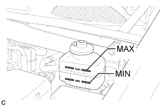
Check the fluid level.
If brake fluid level is lower than the MIN line, check for leaks and inspect the disc brake pads. If necessary, refill the reservoir with brake fluid to the MAX line after repair or replacement.
Brake Fluid SAE J1703 or FMVSS No. 116 DOT 3
-
-
INSPECT FOR BRAKE FLUID LEAK
-
INSTALL V-BANK COVER SUB-ASSEMBLY
-
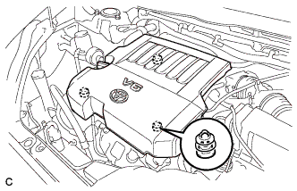
Fit the 3 retainers and install the V-bank cover.
-
-
CONNECT CABLE TO NEGATIVE BATTERY TERMINAL
Note
When disconnecting the cable, some systems need to be initialized after the cable is reconnected. Click here
-
INSPECT BRAKE ACTUATOR WITH INTELLIGENT TESTER
-
PERFORM YAW RATE AND ACCELERATION SENSOR ZERO POINT CALIBRATION
-
CHECK AND CLEAR DTCS