| DTC Code | DTC Name |
|---|---|
| Skid Control Buzzer Circuit |
INSPECTION PROCEDURE
When replacing the brake actuator assembly, perform zero point calibration (Click here).
PROCEDURE
- Click here
PERFORM ACTIVE TEST USING INTELLIGENT TESTER (SKID CONTROL BUZZER)
-
Connect the intelligent tester to the DLC3.
-
Start the engine.
-
Select the Active Test mode on the intelligent tester (Click here).
Table 1. ABS / VSC / TRC: Tester Display Test Part Control Range Diagnostic Note Buzzer Skid control buzzer Buzzer ON / OFF Buzzer can be heard -
Check that the buzzer sounds/stops when turning the skid control buzzer on/off by using the intelligent tester.
Result Result Proceed to Buzzer does not sound or sounds constantly A Buzzer sounds/stops B Tip:If troubleshooting has been carried out according to the Problem Symptoms Table, refer back to the table and proceed to the next step (Click here).
-
- Click here
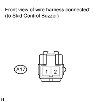
INSPECT SKID CONTROL BUZZER (POWER SOURCE TERMINAL)
-
Turn the ignition switch off.
-
Disconnect the skid control buzzer connector.
-
Turn the ignition switch on (IG).
-
Measure the voltage according to the value(s) in the table below.
Standard voltage Tester Connection Switch Condition Specified Condition A17-2 - Body ground Ignition switch on (IG) 11 to 14 V
- OKClick here
- NGClick here
-
- Click here
INSPECT SKID CONTROL BUZZER
-
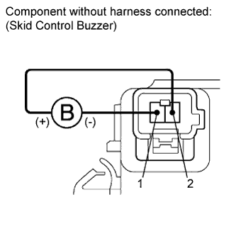
Turn the ignition switch off.
-
Apply battery negative voltage to terminal 1, and battery positive voltage to terminal 2 of the skid control buzzer, and then check that the buzzer sounds.
OK The skid control buzzer sounds.
- OKClick here
- NGClick here
-
- Click here
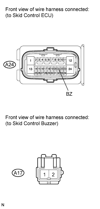
CHECK HARNESS AND CONNECTOR (SKID CONTROL ECU - SKID CONTROL BUZZER)
-
Disconnect the skid control ECU connector.
-
Measure the resistance according to the value(s) in the table below.
Standard resistance Tester Connection Condition Specified Condition A24-21 (BZ) - A17-1 Always Below 1 Ω A24-21 (BZ) - Body ground Always 10 kΩ or higher Tip:If troubleshooting has been carried out according to the Problem Symptoms Table, refer back to the table and proceed to the next step before replacing the part (Click here).
- OKClick here
- NGClick here
-
- Click here
REPLACE BRAKE ACTUATOR ASSEMBLYClick here
- Click here
END
- Click here
REPAIR OR REPLACE HARNESS OR CONNECTOR (POWER SOURCE CIRCUIT)
- Click here
REPLACE SKID CONTROL BUZZERClick here
- Click here
REPAIR OR REPLACE HARNESS OR CONNECTOR