| DTC Code | DTC Name |
|---|---|
| ABS Warning Light Remains ON |
DESCRIPTION
The skid control ECU is connected to the combination meter via CAN communication.
If any of the following is detected, the ABS warning light remains on:
-
The skid control ECU connectors are disconnected from the skid control ECU.
-
There is a malfunction in the skid control ECU internal circuit.
-
There is an open in the harness between the combination meter and the skid control ECU.
-
The ABS control system is defective.
-
For vehicles with the multi-information display, the master caution indicator light will come on and a check ABS message will be displayed on the multi-information display if the ABS control cannot be performed.
-
In some cases, the intelligent tester cannot be used when the skid control ECU is abnormal.
INSPECTION PROCEDURE
When replacing the brake actuator assembly, perform zero point calibration (Click here).
PROCEDURE
- Click here
CHECK CAN COMMUNICATION SYSTEM
-
Check if a CAN communication system DTC is output (Click here).
Result Result Proceed to DTC is not output A DTC is output B
-
- Click here
CHECK IF SKID CONTROL ECU CONNECTOR IS SECURELY CONNECTED
-
Check if the skid control ECU connector is securely connected.
OK The connector is securely connected.
- OKClick here
- NGClick here
-
- Click here
CHECK BATTERY
-
Check the battery voltage.
Standard voltage 11 to 14 V
- OKClick here
- NGClick here
-
- Click here
INSPECT SKID CONTROL ECU (IG1 TERMINAL)
-
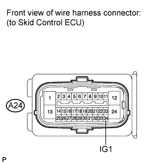
Disconnect the skid control ECU connector.
-
Turn the ignition switch on (IG).
-
Measure the voltage according to the value(s) in the table below.
Standard voltage Tester Connection Switch Condition Specified Condition A24-34 (IG1) - Body ground Ignition switch on (IG) 11 to 14 V
- OKClick here
- NGClick here
-
- Click here
INSPECT SKID CONTROL ECU (GND1 TERMINAL)
-
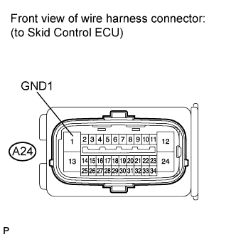
Turn the ignition switch off.
-
Measure the resistance according to the value(s) in the table below.
Standard resistance Tester Connection Condition Specified Condition A24-1 (GND1) - Body ground Always Below 1 Ω
- OKClick here
- NGClick here
-
- Click here
INSPECT COMBINATION METER ASSEMBLY
-
Reconnect the skid control ECU connector.
-
Perform the Active Test of the combination meter (meter CPU) using the intelligent tester (Click here).
-
Check the combination meter.
OK The ABS warning light turns on or off in accordance with the intelligent tester operation. Tip:If troubleshooting has been carried out according to the Problem Symptoms Table, refer back to the table and proceed to the next step before replacing the part (Click here).
- OKClick here
- NGClick here
-
- Click here
REPLACE BRAKE ACTUATOR ASSEMBLYClick here
- Click here
INSPECT CAN COMMUNICATION SYSTEMClick here
- Click here
CONNECT CONNECTOR TO ECU CORRECTLY
- Click here
CHECK OR REPLACE CHARGING SYSTEM OR BATTERY (for 2GR-FE)Click here
- Click here
REPAIR OR REPLACE HARNESS OR CONNECTOR (IG1 CIRCUIT)
- Click here
REPAIR OR REPLACE HARNESS OR CONNECTOR (GND1 CIRCUIT)
- Click here
REPLACE COMBINATION METER ASSEMBLYClick here