VEHICLE STABILITY CONTROL SYSTEM ABS Warning Light Remains ON
DESCRIPTION
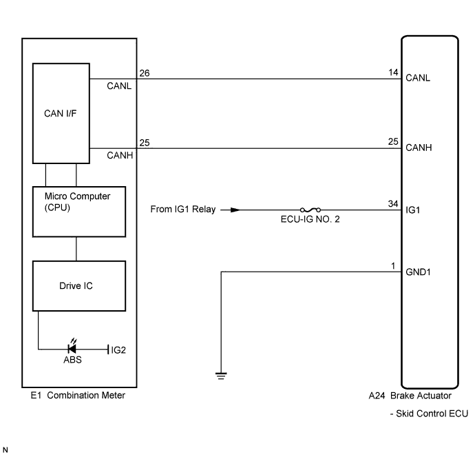
The skid control ECU is connected to the combination meter via CAN communication.
If any of the following is detected, the ABS warning light remains on:
-
The skid control ECU connectors are disconnected from the skid control ECU.
-
There is a malfunction in the skid control ECU internal circuit.
-
There is an open in the harness between the combination meter and the skid control ECU.
-
The ABS control system is defective.
Tech Tips
-
For vehicles with the multi-information display, the master caution indicator light will come on and a check ABS message will be displayed on the multi-information display if the ABS control cannot be performed.
-
In some cases, the intelligent tester cannot be used when the skid control ECU is abnormal.
WIRING DIAGRAM
INSPECTION PROCEDURE
Note
When replacing the brake actuator assembly, perform zero point calibration Click here.
PROCEDURE
-
CHECK CAN COMMUNICATION SYSTEM
-
Check if a CAN communication system DTC is output Click here.
Result Result Proceed to DTC is not output A DTC is output B
B 
INSPECT CAN COMMUNICATION SYSTEM Click here
A 
-
-
CHECK IF SKID CONTROL ECU CONNECTOR IS SECURELY CONNECTED
-
Check if the skid control ECU connector is securely connected.
OK The connector is securely connected.
NG
CONNECT CONNECTOR TO ECU CORRECTLY
OK
-
-
CHECK BATTERY
-
Check the battery voltage.
Standard voltage 11 to 14 V
NG
CHECK OR REPLACE CHARGING SYSTEM OR BATTERY (for 2GR-FE) Click here
OK
-
-
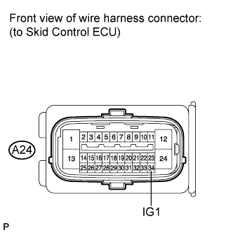
INSPECT SKID CONTROL ECU (IG1 TERMINAL)
-
Disconnect the skid control ECU connector.
-
Turn the ignition switch on (IG).
-
Measure the voltage according to the value(s) in the table below.
Standard voltage Tester Connection Switch Condition Specified Condition A24-34 (IG1) - Body ground Ignition switch on (IG) 11 to 14 V
NG
REPAIR OR REPLACE HARNESS OR CONNECTOR (IG1 CIRCUIT)
OK
-
-
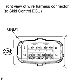
INSPECT SKID CONTROL ECU (GND1 TERMINAL)
-
Turn the ignition switch off.
-
Measure the resistance according to the value(s) in the table below.
Standard resistance Tester Connection Condition Specified Condition A24-1 (GND1) - Body ground Always Below 1 Ω
NG
REPAIR OR REPLACE HARNESS OR CONNECTOR (GND1 CIRCUIT)
OK
-
-
INSPECT COMBINATION METER ASSEMBLY
-
Reconnect the skid control ECU connector.
-
Perform the Active Test of the combination meter (meter CPU) using the intelligent tester Click here.
-
Check the combination meter.
OK The ABS warning light turns on or off in accordance with the intelligent tester operation. Tech Tips
If troubleshooting has been carried out according to the Problem Symptoms Table, refer back to the table and proceed to the next step before replacing the part Click here.
NG
REPLACE COMBINATION METER ASSEMBLY Click here
OK 
REPLACE BRAKE ACTUATOR ASSEMBLY Click here
-