VEHICLE STABILITY CONTROL SYSTEM, Diagnostic DTC:U0073, U0100, U0123, U0124, U0126
| DTC Code | DTC Name |
|---|---|
| U0073 | Control Module Communication Bus OFF |
| U0100 | Lost Communication with ECM / PCM |
| U0123 | Lost Communication with Yaw Rate Sensor Module |
| U0124 | Lost Communication with Lateral Acceleration Sensor Module |
| U0126 | Lost Communication with Steering Angle Sensor Module |
DESCRIPTION
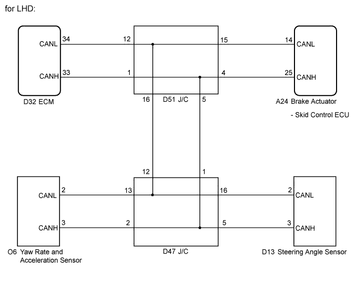
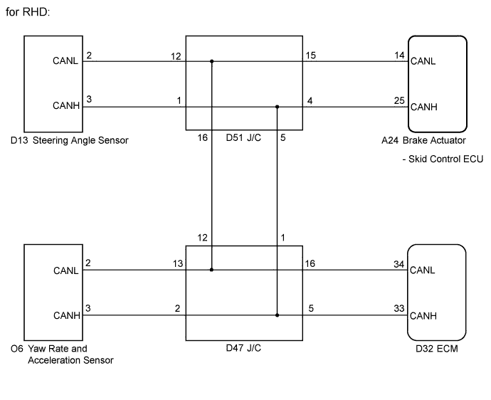
The skid control ECU receives signals from the ECM, steering angle sensor, and yaw rate and acceleration sensor via the CAN communication system.
| DTC Code | DTC Detection Condition | Trouble Area |
|---|---|---|
| U0073 | Any of the following is detected:
|
CAN communication system |
| U0100 | The IG1 terminal voltage is between 10 and 17.4 V and the vehicle speed is 15 km/h (9 mph) or more, data cannot be received from the ECM for 2 seconds or more. | CAN communication system (Skid control ECU to ECM) |
| U0123 | Either of the following is detected:
|
CAN communication system (Skid control ECU to yaw rate and acceleration sensor) |
| U0124 | Either of the following is detected:
|
CAN communication system (Skid control ECU to yaw rate and acceleration sensor) |
| U0126 | Either of the following is detected:
|
CAN communication system (Skid control ECU to steering angle sensor) |
WIRING DIAGRAM
INSPECTION PROCEDURE
PROCEDURE
-
CHECK HARNESS AND CONNECTOR (MOMENTARY INTERRUPTION)
-
Using the intelligent tester, check for any momentary interruption in the wire harness and connector corresponding to the DTC Click here.
ABS / VSC / TRC: Tester Display Measurement Item/Range Normal Condition Diagnostic Note EFI Communication Open EFI communication open detection / ERROR or NORMAL ERROR: Momentary interruption
NORMAL: Normal
- Yaw Rate Open Yaw rate sensor open detection / ERROR or NORMAL ERROR: Momentary interruption
NORMAL: Normal
- Steering Open Steering sensor open detection / ERROR or NORMAL ERROR: Momentary interruption
NORMAL: Normal
- Result Result Proceed to There is a constant open circuit A There are no momentary interruptions B There are momentary interruptions C Tech Tips
Perform the above inspection before removing the sensor and connector.
B 
RECONFIRM DTC Click here
C
REPAIR OR REPLACE HARNESS OR CONNECTOR Click here
A 
-
-
CHECK IF EACH SENSOR AND ECM CONNECTOR IS SECURELY CONNECTED
-
Turn the ignition switch off.
-
Check if each sensor or ECM connector is securely connected.
OK Each connector is securely connected.
NG 
CONNECT CONNECTOR TO EACH SENSOR OR ECM CORRECTLY
OK
-
-
RECONFIRM DTC
-
Turn the ignition switch off.
-
Record the output DTCs (for ABS, VSC system and/or CAN communication system) Click here for ABS and VSC system, or Click here for CAN communication system).
Tech Tips
If CAN communication system DTCs and the relevant sensor DTCs are output simultaneously, troubleshoot the relevant sensor DTCs (for ABS and/or VSC system) after the CAN communication system returns to normal.
Result Result Proceed to DTC is not output A DTC (ABS and/or VSC system DTC) is output B DTC (CAN communication system DTC) is output C
B
REPAIR CIRCUIT INDICATED BY OUTPUT DTC Click here
C
INSPECT CAN COMMUNICATION SYSTEM Click here
A 
CHECK FOR INTERMITTENT PROBLEMS (SYMPTOM SIMULATION) Click here
-
-
REPAIR OR REPLACE HARNESS OR CONNECTOR
-
Turn the ignition switch off.
-
Repair or replace the harness or connector.
-
Check for any momentary interruption between the skid control ECU and each sensor or ECM Click here.
-
Check that there are no momentary interruptions.
NEXT
-
-
RECONFIRM DTC
-
Turn the ignition switch off.
-
Clear the DTCs Click here.
-
Start the engine.
-
Drive the vehicle and turn the steering wheel to the right and left at a speed of 15 km/h (9 mph) or more.
-
Check that no CAN communication system DTC is output Click here.
-
If ABS and/or VSC system DTCs are output, record them.
Result Result Proceed to DTC is not output A DTC (ABS and/or VSC system DTC) is output B DTC (CAN communication system DTC) is output C Tech Tips
The CAN communication system must be normal when performing troubleshooting for each sensor DTC (for ABS and/or VSC system).
B
REPAIR CIRCUIT INDICATED BY OUTPUT DTC Click here
C
INSPECT CAN COMMUNICATION SYSTEM Click here
A
END
-