VEHICLE STABILITY CONTROL SYSTEM, Diagnostic DTC:C1381
| DTC Code | DTC Name |
|---|---|
| C1381 | Acceleration Sensor Power Supply Voltage Malfunction |
DESCRIPTION
The skid control ECU receives signals from the yaw rate and acceleration sensor via the CAN communication system.
The yaw rate sensor has a built-in acceleration sensor and detects the vehicle's condition using 2 circuits (GL1, GL2).
If there is trouble in the bus lines between the yaw rate and acceleration sensor and the CAN communication system, DTCs U0123 (malfunction in CAN communication with the yaw rate sensor) and U0124 (malfunction in CAN communication with the acceleration sensor) are set.
These DTCs are also output when calibration has not been completed.
| DTC Code | DTC Detection Condition | Trouble Area |
|---|---|---|
| C1381 | At a vehicle speed of more than 3 km/h (2 mph), an acceleration sensor power source malfunction signal is received for 10 seconds or more. |
|
WIRING DIAGRAM
Refer to DTCs C1232, C1243 and C1245 Click here.
INSPECTION PROCEDURE
Note
When replacing the yaw rate and acceleration sensor, perform zero point calibration Click here.
Tech Tips
When U0123, U0124 and/or U0126 is output together with C1381, inspect and repair the trouble areas indicated by U0123, U0124 and/or U0126 first Click here.
PROCEDURE
-
INSPECT YAW RATE AND ACCELERATION SENSOR (IG TERMINAL)
-
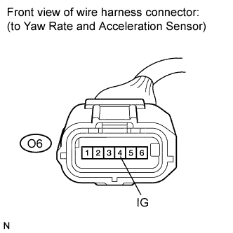
Make sure that there is no looseness at the locking part and the connecting part of the connector.
-
Disconnect the yaw rate and acceleration sensor connector.
-
Turn the ignition switch on (IG).
-
Measure the voltage according to the value(s) in the table below.
Standard voltage Tester Connection Switch Condition Specified Condition O6-4 (IG) - Body ground Ignition switch on (IG) 11 to 14 V
NG 
REPAIR OR REPLACE HARNESS OR CONNECTOR (IG CIRCUIT)
OK 
-
-
INSPECT YAW RATE AND ACCELERATION SENSOR (GND TERMINAL)
-
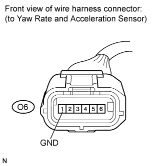
Turn the ignition switch off.
-
Measure the resistance according to the value(s) in the table below.
Standard resistance Tester Connection Condition Specified Condition O6-1 (GND) - Body ground Always Below 1 Ω
NG
REPAIR OR REPLACE HARNESS OR CONNECTOR (GND CIRCUIT)
OK
-
-
RECONFIRM DTC
-
Reconnect the yaw rate and acceleration sensor connector.
-
Clear the DTCs Click here.
-
Start the engine.
-
Drive the vehicle at a speed of 3 km/h (2 mph) or more for at least 10 seconds.
-
Check if the same DTC is recorded Click here.
Result Result Proceed to DTC (C1381) is not output A DTC (C1381) is output B Note
Check the yaw rate and acceleration sensor signal after replacement Click here.
Tech Tips
If troubleshooting has been carried out according to the Problem Symptoms Table, refer back to the table and proceed to the next step Click here.
B
REPLACE YAW RATE AND ACCELERATION SENSOR Click here
A 
CHECK FOR INTERMITTENT PROBLEMS (SYMPTOM SIMULATION) Click here
-