VEHICLE STABILITY CONTROL SYSTEM, Diagnostic DTC:C1337
| DTC Code | DTC Name |
|---|---|
| C1337 | Diameter of the Tire is not Uniform |
DESCRIPTION
The skid control ECU measures the speed of each wheel by receiving signals from the speed sensor.
These signals are used for recognizing that all 4 wheels are operating properly.
Therefore, all wheel signals must be equal.
| DTC Code | DTC Detection Condition | Trouble Area |
|---|---|---|
| C1337 | The following occurs in 3 consecutive trips: At a vehicle speed of 20 km/h (12 mph) or more, there is a 20 % difference or greater in the average speed between the front wheels and rear wheels for 20 seconds or more. |
|
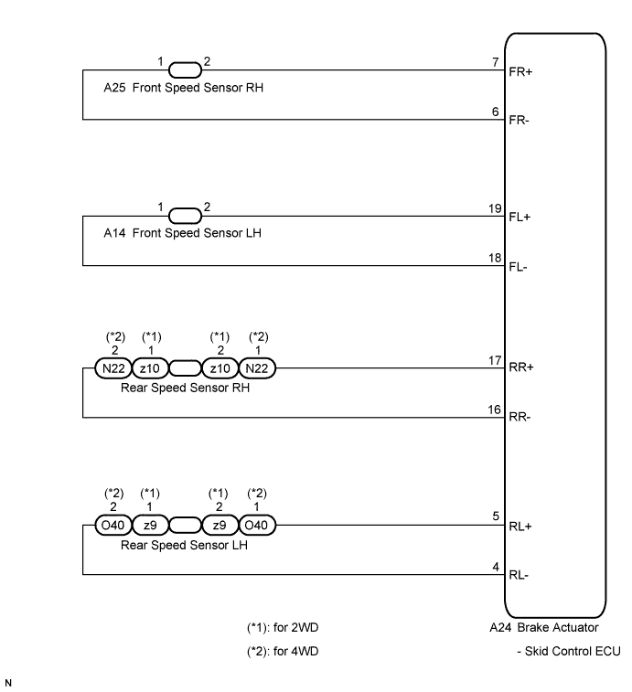
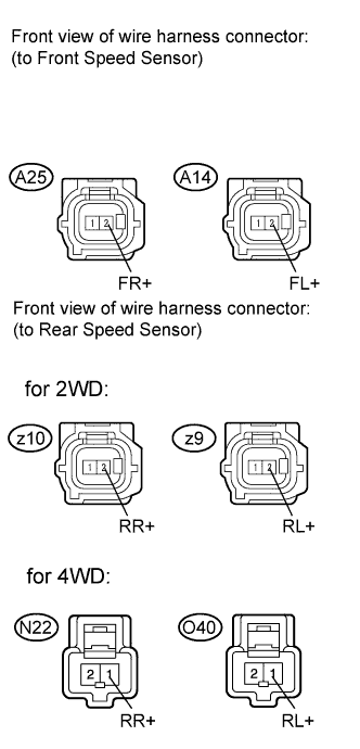
WIRING DIAGRAM
INSPECTION PROCEDURE
Note
When replacing the brake actuator assembly, perform zero point calibration Click here.
PROCEDURE
-
CHECK TIRES
-
Check the size and condition of all 4 wheels Click here.
Tech Tips
The DTC is output when tire deformation or a difference in tire size is detected.
OK The diameter of all 4 tires and air pressure are the same. Result Result Proceed to OK (Except for rear 2WD) A OK (for rear 2WD) B NG C
B 
INSPECT EACH SPEED SENSOR Click here
C 
REPLACE TIRES SO THAT ALL FOUR TIRES ARE SAME SIZE
A 
-
-
CHECK EACH SPEED SENSOR TIP
-
Remove the front speed sensor or the rear speed sensor Click here for front, or Click here for rear).
-
Check the speed sensor tip.
OK No scratches, oil, or foreign matter on the sensor tip. Note
Check the speed sensor signal after cleaning or replacement Click here.
NG
CLEAN OR REPLACE EACH SPEED SENSOR
OK
-
-
CHECK EACH SPEED SENSOR ROTOR
-
Remove the front speed sensor rotor or the rear speed sensor rotor Click here for front, or Click here for rear).
-
Check the speed sensor rotor.
OK No scratches, oil, or foreign matter on the rotors. Note
Check the speed sensor signal after cleaning or replacement Click here.
Tech Tips
-
If the front speed sensor rotor needs to be replaced, replace it together with the front drive shaft assembly.
-
If the rear speed sensor rotor needs to be replaced, replace it together with the rear drive shaft assembly.
-
NG
CLEAN OR REPLACE EACH SPEED SENSOR ROTOR
OK
-
-
INSPECT EACH SPEED SENSOR
-
Install the speed sensor and the speed sensor rotor.
-
Make sure that there is no looseness at the locking part and the connecting part of the connectors.
-
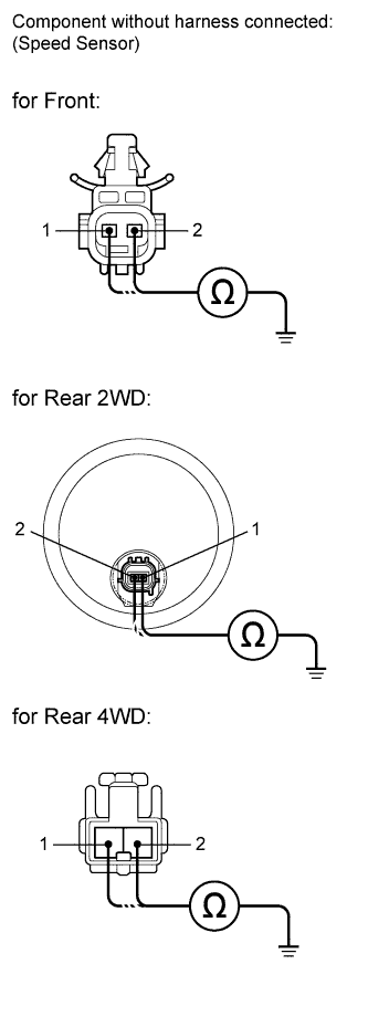
Disconnect each speed sensor connector.
-
Measure the resistance according to the value(s) in the table below.
Standard resistance for 2WD RH Tester Connection Condition Specified Condition 2 (FR+) - Body ground Always 10 kΩ or higher 1 (FR-) - Body ground Always 10 kΩ or higher 2 (RR+) - Body ground Always 10 kΩ or higher 1 (RR-) - Body ground Always 10 kΩ or higher for 4WD RH Tester Connection Condition Specified Condition 2 (FR+) - Body ground Always 10 kΩ or higher 1 (FR-) - Body ground Always 10 kΩ or higher 1 (RR+) - Body ground Always 10 kΩ or higher 2 (RR-) - Body ground Always 10 kΩ or higher for 2WD LH Tester Connection Condition Specified Condition 2 (FL+) - Body ground Always 10 kΩ or higher 1 (FL-) - Body ground Always 10 kΩ or higher 2 (RL+) - Body ground Always 10 kΩ or higher 1 (RL-) - Body ground Always 10 kΩ or higher for 4WD LH Tester Connection Condition Specified Condition 2 (FL+) - Body ground Always 10 kΩ or higher 1 (FL-) - Body ground Always 10 kΩ or higher 1 (RL+) - Body ground Always 10 kΩ or higher 2 (RL-) - Body ground Always 10 kΩ or higher Result Result Proceed to OK (for rear 2WD) A OK (Except for rear 2WD) B NG C Note
Check the speed sensor signal after replacement Click here.
B
CHECK HARNESS AND CONNECTOR (SKID CONTROL ECU - EACH SPEED SENSOR) Click here
C
REPLACE EACH SPEED SENSOR
A
-
-
CHECK HARNESS AND CONNECTOR (SKID CONTROL SENSOR WIRE)
-
Make sure that there is no looseness at the locking part and the connecting part of the connectors.
-
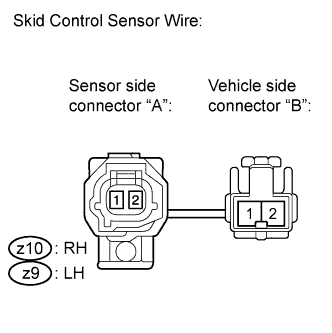
Disconnect the skid control sensor wire.
-
Measure the resistance according to the value(s) in the table below.
Standard resistance for RH Tester Connection Condition Specified Condition z10 ("A"-2) - z10 ("B"-1) Always Below 1 Ω z10 ("A"-2) - z10 ("B"-2) Always 10 kΩ or higher z10 ("A"-2) - Body ground Always 10 kΩ or higher z10 ("A"-1) - z10 ("B"-2) Always Below 1 Ω z10 ("A"-1) - z10 ("B"-1) Always 10 kΩ or higher z10 ("A"-1) - Body ground Always 10 kΩ or higher for LH Tester Connection Condition Specified Condition z9 ("A"-2) - z9 ("B"-1) Always Below 1 Ω z9 ("A"-2) - z9 ("B"-2) Always 10 kΩ or higher z9 ("A"-2) - Body ground Always 10 kΩ or higher z9 ("A"-1) - z9 ("B"-2) Always Below 1 Ω z9 ("A"-1) - z9 ("B"-1) Always 10 kΩ or higher z9 ("A"-1) - Body ground Always 10 kΩ or higher Note
Check the speed sensor signal after replacement Click here.
NG
REPLACE SKID CONTROL SENSOR WIRE
OK
-
-
CHECK HARNESS AND CONNECTOR (SKID CONTROL ECU - EACH SPEED SENSOR)
-
Reconnect the skid control sensor wire (for 2WD).
-
Make sure that there is no looseness at the locking part and the connecting part of the connector.
-
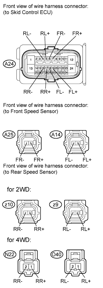
Disconnect the skid control ECU connector.
-
Measure the resistance according to the value(s) in the table below.
Standard resistance for 2WD RH Tester Connection Condition Specified Condition A24-7 (FR+) - A25-2 (FR+) Always Below 1 Ω A24-7 (FR+) - Body ground Always 10 kΩ or higher A24-6 (FR-) - A25-1 (FR-) Always Below 1 Ω A24-6 (FR-) - Body ground Always 10 kΩ or higher A24-17 (RR+) - z10-2 (RR+) Always Below 1 Ω A24-17 (RR+) - Body ground Always 10 kΩ or higher A24-16 (RR-) - z10-1 (RR-) Always Below 1 Ω A24-16 (RR-) - Body ground Always 10 kΩ or higher for 4WD RH Tester Connection Condition Specified Condition A24-7 (FR+) - A25-2 (FR+) Always Below 1 Ω A24-7 (FR+) - Body ground Always 10 kΩ or higher A24-6 (FR-) - A25-1 (FR-) Always Below 1 Ω A24-6 (FR-) - Body ground Always 10 kΩ or higher A24-17 (RR+) - N22-1 (RR+) Always Below 1 Ω A24-17 (RR+) - Body ground Always 10 kΩ or higher A24-16 (RR-) - N22-2 (RR-) Always Below 1 Ω A24-16 (RR-) - Body ground Always 10 kΩ or higher for 2WD LH Tester Connection Condition Specified Condition A24-19 (FL+) - A14-2 (FL+) Always Below 1 Ω A24-19 (FL+) - Body ground Always 10 kΩ or higher A24-18 (FL-) - A14-1 (FL-) Always Below 1 Ω A24-18 (FL-) - Body ground Always 10 kΩ or higher A24-5 (RL+) - z9-2 (RL+) Always Below 1 Ω A24-5 (RL+) - Body ground Always 10 kΩ or higher A24-4 (RL-) - z9-1 (RL-) Always Below 1 Ω A24-4 (RL-) - Body ground Always 10 kΩ or higher for 4WD LH Tester Connection Condition Specified Condition A24-19 (FL+) - A14-2 (FL+) Always Below 1 Ω A24-19 (FL+) - Body ground Always 10 kΩ or higher A24-18 (FL-) - A14-1 (FL-) Always Below 1 Ω A24-18 (FL-) - Body ground Always 10 kΩ or higher A24-5 (RL+) - O40-1 (RL+) Always Below 1 Ω A24-5 (RL+) - Body ground Always 10 kΩ or higher A24-4 (RL-) - O40-2 (RL-) Always Below 1 Ω A24-4 (RL-) - Body ground Always 10 kΩ or higher
NG
REPAIR OR REPLACE HARNESS OR CONNECTOR
OK
-
-
INSPECT SKID CONTROL ECU (SENSOR INPUT)
-
Reconnect the skid control ECU connector.
-
Turn the ignition switch on (IG).
-
Measure the voltage according to the value(s) in the table below.
Standard voltage for 2WD RH Tester Connection Switch Condition Specified Condition A25-2 (FR+) - Body ground Ignition switch on (IG) 8 to 14 V z10-2 (RR+) - Body ground Ignition switch on (IG) 8 to 14 V for 4WD RH Tester Connection Switch Condition Specified Condition A25-2 (FR+) - Body ground Ignition switch on (IG) 8 to 14 V N22-1 (RR+) - Body ground Ignition switch on (IG) 8 to 14 V for 2WD LH Tester Connection Switch Condition Specified Condition A14-2 (FL+) - Body ground Ignition switch on (IG) 8 to 14 V z9-2 (RL+) - Body ground Ignition switch on (IG) 8 to 14 V for 4WD LH Tester Connection Switch Condition Specified Condition A14-2 (FL+) - Body ground Ignition switch on (IG) 8 to 14 V O40-1 (RL+) - Body ground Ignition switch on (IG) 8 to 14 V
NG
REPLACE BRAKE ACTUATOR ASSEMBLY Click here
OK
-
-
RECONFIRM DTC
-
Turn the ignition switch off.
-
Reconnect the speed sensor connectors.
-
Clear the DTCs Click here.
-
Start the engine.
-
Drive the vehicle at a speed of 40 km/h (25 mph) or more for at least 60 seconds.
-
Check if the same DTC is recorded Click here.
Result Result Proceed to DTC (C1337) is output (Except for rear 2WD) A DTC (C1337) is output (for rear 2WD) B DTC (C1337) is not output C
B
REPLACE REAR SPEED SENSOR AND REAR SPEED SENSOR ROTOR Click here
C
CHECK FOR INTERMITTENT PROBLEMS (SYMPTOM SIMULATION) Click here
A
-
-
REPLACE EACH SPEED SENSOR
-
Turn the ignition switch off.
-
Replace the front speed sensor or the rear speed sensor Click here for front, or Click here for rear).
Note
Check the speed sensor signal after replacement Click here.
NEXT
-
-
RECONFIRM DTC
-
Clear the DTCs Click here.
-
Start the engine.
-
Drive the vehicle at a speed of 40 km/h (25 mph) or more for at least 60 seconds.
-
Check if the same DTC is recorded Click here.
Result Result Proceed to DTC (C1337) is output A DTC (C1337) is not output B
B
END
A
-
-
REPLACE EACH SPEED SENSOR ROTOR
-
Turn the ignition switch off.
-
Replace the front drive shaft assembly (front speed sensor rotor) or rear drive shaft assembly (rear speed sensor rotor) Click here for front, or Click here for rear).
Tech Tips
-
If the front speed sensor rotor needs to be replaced, replace it together with the front drive shaft assembly.
-
If the rear speed sensor rotor needs to be replaced, replace it together with the rear drive shaft assembly.
Note
Check the speed sensor signal after replacement Click here.
-
NEXT
-
-
RECONFIRM DTC
-
Clear the DTCs Click here.
-
Start the engine.
-
Drive the vehicle at a speed of 40 km/h (25 mph) or more for at least 60 seconds.
-
Check if the same DTC is recorded Click here.
Result Result Proceed to DTC (C1337) is output A DTC (C1337) is not output B
B
END
A 
REPLACE BRAKE ACTUATOR ASSEMBLY Click here
-
-
REPLACE REAR SPEED SENSOR AND REAR SPEED SENSOR ROTOR
-
Turn the ignition switch off.
-
Replace the rear speed sensor Click here.
-
Replace the rear axle hub and bearing assembly (rear speed sensor rotor) Click here.
Tech Tips
The rear speed sensor rotor is incorporated into the rear axle hub and bearing assembly.
If the rear speed sensor rotor needs to be replaced, replace it together with the rear axle hub and bearing assembly with rear speed sensor.
Note
Check the speed sensor signal after replacement Click here.
NEXT
-
-
RECONFIRM DTC
-
Clear the DTCs Click here.
-
Start the engine.
-
Drive the vehicle at a speed of 40 km/h (25 mph) or more for at least 60 seconds.
-
Check if the same DTC is recorded Click here.
Result Result Proceed to DTC (C1337) is output A DTC (C1337) is not output B
B
END
A
REPLACE BRAKE ACTUATOR ASSEMBLY Click here
-