VEHICLE STABILITY CONTROL SYSTEM, Diagnostic DTC:C1279
| DTC Code | DTC Name |
|---|---|
| C1279 | Acceleration Sensor Output Voltage Malfunction (Test Mode DTC) |
DESCRIPTION
DTC C1279 can be deleted when the yaw rate and acceleration sensor sends a yaw rate and/or acceleration signal or when Test Mode ends. DTC C1279 is output only in Test Mode.
| DTC Code | DTC Detection Condition | Trouble Area |
|---|---|---|
| C1279 | Detected only during Test Mode. |
|
WIRING DIAGRAM
Refer to DTCs C1232, C1243 and C1245 Click here.
INSPECTION PROCEDURE
Note
When replacing the yaw rate and acceleration sensor, perform zero point calibration Click here.
PROCEDURE
-
CHECK YAW RATE AND ACCELERATION SENSOR INSTALLATION
-
Check that the yaw rate and acceleration sensor has been installed properly Click here.
OK The sensor should be tightened to the specified torque. The sensor should not be installed in a tilted position.
NG 
INSTALL YAW RATE AND ACCELERATION SENSOR CORRECTLY Click here
OK 
-
-
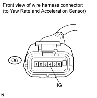
INSPECT YAW RATE AND ACCELERATION SENSOR (IG TERMINAL)
-
Make sure that there is no looseness at the locking part and the connecting part of the connectors.
-
Disconnect the yaw rate and acceleration sensor connector.
-
Turn the ignition switch on (IG).
-
Measure the voltage according to the value(s) in the table below.
Standard voltage Tester Connection Switch Condition Specified Condition O6-4 (IG) - Body ground Ignition switch on (IG) 11 to 14 V
NG
REPAIR OR REPLACE HARNESS OR CONNECTOR (IG CIRCUIT)
OK
-
-
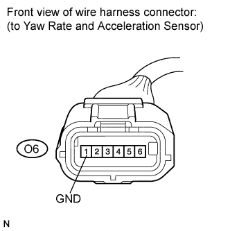
INSPECT YAW RATE AND ACCELERATION SENSOR (GND TERMINAL)
-
Turn the ignition switch off.
-
Measure the resistance according to the value(s) in the table below.
Standard resistance Tester Connection Condition Specified Condition O6-1 (GND) - Body ground Always Below 1 Ω Note
Check the yaw rate and acceleration sensor signal after replacement Click here.
NG
REPAIR OR REPLACE HARNESS OR CONNECTOR (GND CIRCUIT)
OK 
REPLACE YAW RATE AND ACCELERATION SENSOR Click here
-