VEHICLE STABILITY CONTROL SYSTEM DIAGNOSIS SYSTEM
-
DESCRIPTION
When troubleshooting a vehicle with the diagnosis system, the only difference from the usual troubleshooting procedure is connecting the intelligent tester to the vehicle and reading various data output from the vehicle's skid control ECU.
The skid control ECU records DTCs when the computer detects a malfunction in the computer itself or in its circuits.
To check the DTCs, connect the intelligent tester to the DLC3 on the vehicle. The intelligent tester enables you to erase the DTCs, activate the various actuators, and check the Freeze Frame Data and Data List.
-
Check the battery voltage.
If the voltage is below 11 V, recharge the battery before proceeding to the next step.
-
Check the DLC3 Click here.
-
-
DIAGNOSIS
-
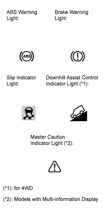
If the skid control ECU detects a malfunction, the ABS warning, brake warning, slip indicator, and downhill assist control indicator (for 4WD) lights will come on in order to warn the driver.
For vehicles with the multi-information display, the master caution indicator light will come on and a warning message will be displayed on the multi-information display if any of the EBD system, BA system, or TRC system is malfunctioning or if the ABS control or VSC cannot be performed.
The table below indicates which lights will come on when there is a malfunction in a particular function.
Item / Trouble Area ABS EBD BA TRC VSC Downhill assist control (*1) Hill-start assist control Skid control ECU ABS warning light ○ ○ ○ - - - - ○ Brake warning light - ○ - - - - - ○ Slip indicator light ○ ○ ○ ○ ○ ○ ○ ○ Downhill assist control indicator light (*1) ●
(Downhill assist control switch ON)
●
(Downhill assist control switch ON)
●
(Downhill assist control switch ON)
●
(Downhill assist control switch ON)
●
(Downhill assist control switch ON)
●
(Downhill assist control switch ON)
●
(Downhill assist control switch ON)
●
(Downhill assist control switch ON)
Master caution indicator light (*2) ○ ○ ○ ○ ○ ○ ○ ○ Multi-information display (*2) ○ ○ ○ - - ○ ○ ○ (*1): for 4WD
(*2): Models with multi-information display
○: Light or display ON
●: Light ON (Blinking)
-: Light or display OFF
Tech Tips
-
The DTCs are simultaneously stored in the memory.
The DTCs can be read by connecting SST between terminals TC and CG of the DLC3 and observing the blinking pattern of the ABS warning and slip indicator lights, or by connecting the intelligent tester Click here.
-
This system has a Test Mode (signal check) function.
The DTCs can be read by connecting SST between terminals TS and CG of the DLC3 and observing the blinking pattern of the ABS warning and slip indicator lights, or by connecting the intelligent tester Click here.
-
-
-
WARNING LIGHT AND INDICATOR LIGHT INITIAL CHECK
-
Release the parking brake.
Note
When releasing the parking brake, move the shift lever to the P position for safety.
Tech Tips
When the parking brake is applied or the level of the brake fluid is low, the brake warning light comes on.
-
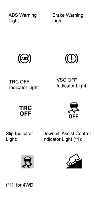
When the ignition switch is turned on (IG), check that the ABS warning, brake warning, TRC OFF indicator, VSC OFF indicator, slip indicator and downhill assist control indicator (for 4WD) lights come on for approximately 3 seconds.
Tech Tips
If the warning light and indicator light check result is not normal, proceed to troubleshooting for the ABS warning, brake warning, TRC OFF indicator, VSC OFF indicator, slip indicator and downhill assist control indicator (for 4WD) light circuits.
If the indicator remains on or does not come on, proceed to troubleshooting for the light circuits listed below.
Trouble Area See procedure ABS warning light circuit (Remains on) ABS warning light circuit (Does not come on) Brake warning light circuit (Remains on) Brake warning light circuit (Does not come on) TRC OFF indicator light circuit (Remains on) TRC OFF indicator light circuit (Does not come on) VSC OFF indicator light circuit (Remains on) VSC OFF indicator light circuit (Does not come on) Slip indicator light circuit (Remains on) Slip indicator light circuit (Does not come on) Downhill assist control indicator light circuit (Remains on) Downhill assist control indicator light circuit (Does not come on)
-
-
SYMPTOM SIMULATION
Tech Tips
The most difficult case in troubleshooting is when no symptoms occur. In such cases, a thorough customer problem analysis must be carried out. Then the same or similar conditions and environment in which the problem occurred in the customer's vehicle should be reproduced. No matter how experienced or skilled a technician may be, if he/she proceeds to troubleshooting without confirming the problem symptoms, he/she will likely overlook something important and make a wrong guess at some points in the repair operation. This leads to a standstill in troubleshooting.
-
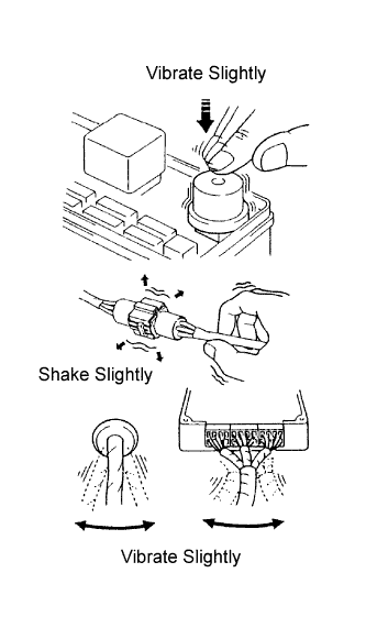
Vibration method: When vibration seems to be the major cause.
Tech Tips
Perform the simulation method only during the primary check period (for approximately 6 seconds after the ignition switch is turned on (IG)).
-
Slightly vibrate the part of the sensor considered to be the problem cause with your fingers and check whether the malfunction occurs.
-
Slightly shake the connector vertically and horizontally.
Tech Tips
Shaking the relays too strongly may result in open relays.
-
Slightly shake the wire harness vertically and horizontally. The connector joint and fulcrum of the vibration are the major areas to be checked thoroughly.
-
-