VEHICLE STABILITY CONTROL SYSTEM SYSTEM DESCRIPTION
-
FUNCTION DESCRIPTION
Tech Tips
-
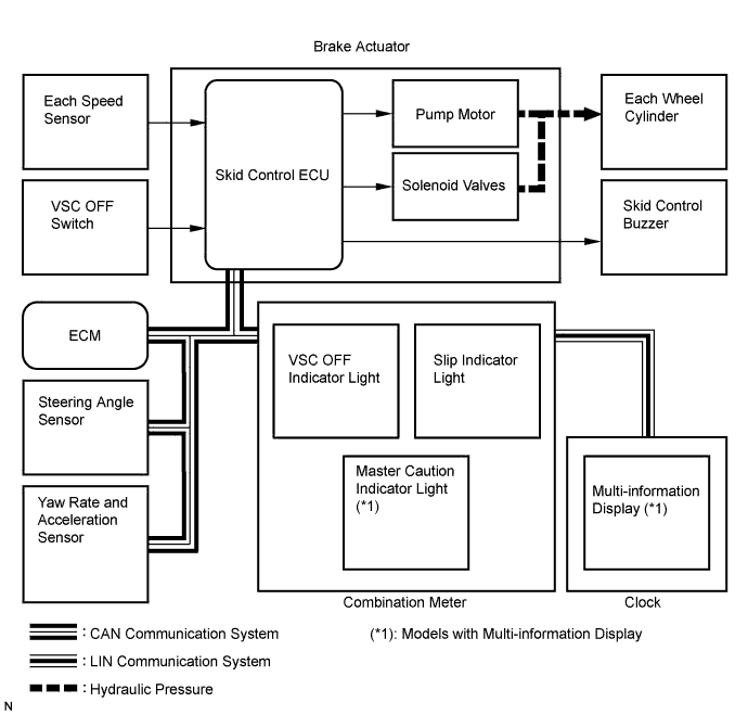
The skid control ECU is located within the brake actuator assembly.
-
The yaw rate sensor and acceleration sensor are combined in a single unit. This unit communicates with the skid control ECU through CAN communication.
-
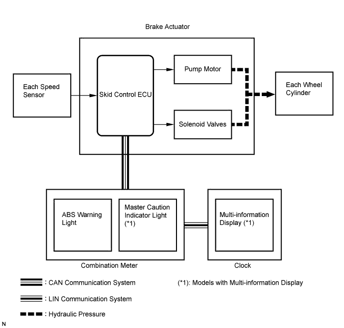
ABS (Anti-lock Brake System)
The ABS helps prevent the wheels from locking when the brakes are applied firmly or when braking on a slippery surface.
-
Operation description
The skid control ECU detects wheel lock based on speed signals received from the wheel speed sensors. Based on this information, the skid control ECU controls the pump motor and solenoid valves. The pump motor and solenoid valves are used to prevent wheel lock by controlling the hydraulic pressure applied to the brakes at each wheel. The ABS warning light will come on when the system is malfunctioning.
Tech Tips
For vehicles with the multi-information display, the master caution indicator light will come on and a check ABS message will be displayed on the multi-information display if the ABS control cannot be performed.
-
-
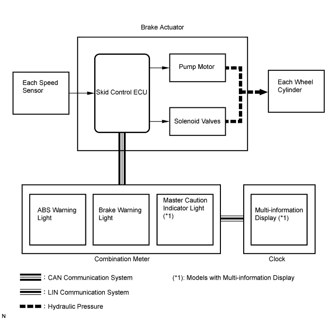
EBD (Electronic Brake force Distribution)
The EBD control utilizes ABS, and performs proper brake force distribution between the front and rear wheels in accordance with driving conditions.
When braking while cornering, it also controls the brake force distribution between the right and left wheels, helping to maintain vehicle behavior.
-
Operation description
The skid control ECU receives a speed signal from each wheel speed sensor, and uses these signals to detect locking of the wheels. The ECU uses this information in order to determine appropriate control of the solenoid valves.
The solenoid valves control the hydraulic pressure applied to the brake cylinder at each wheel. In this way, the solenoid valves are used to control the brake power split between the front and rear, and left and right wheels. The ABS waning and brake warning lights will come on if there is a malfunction in the EBD system.
Tech Tips
For vehicles with the multi-information display, the master caution indicator light will come on and a brake malfunction message will be displayed on the multi-information display if the EBD system is malfunctioning.
-
-
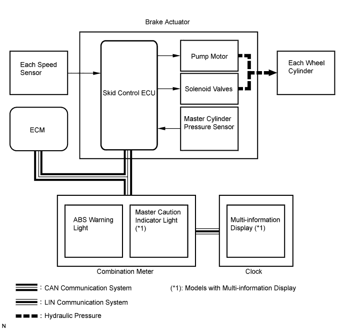
BA (Brake Assist)
The primary purpose of the brake assist system is to provide auxiliary brake force to assist a driver who cannot generate a large enough brake force during emergency braking, thus helping to maximize the brake performance of the vehicle.
-
Operation description
The skid control ECU receives a speed signal from each speed sensor and a fluid pressure signal from the master cylinder pressure sensor to determine whether brake assist is necessary. If brake assist is necessary, the skid control ECU sends control signals to the pump motor and solenoid. The pump and the solenoid valves then control the pressure applied to each wheel cylinder.
The ABS warning light will come on to indicate a malfunction in the BA system.
Tech Tips
For vehicles with the multi-information display, the master caution indicator light will come on and a check ABS message will be displayed on the multi-information display if the BA system is malfunctioning.
-
-
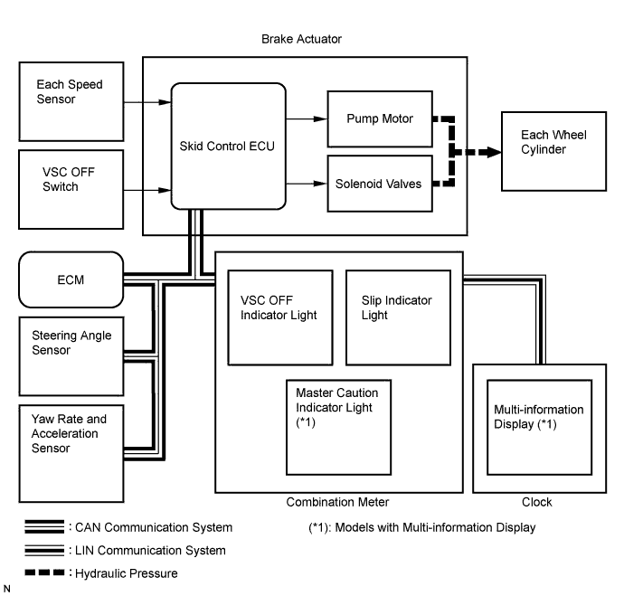
TRC (Traction Control)
The TRC system helps prevent the drive wheels from slipping when the driver depresses the accelerator pedal excessively when starting off or accelerating on a slippery surface.
-
Operation description
The skid control ECU detects wheelspin by receiving signals from each speed sensor and the ECM via CAN communication. The skid control ECU sends signals via CAN communication to the ECM in order to control engine torque. The skid control ECU controls brake hydraulic pressure using the pump and solenoid valves.
The slip indicator light blinks when the system is operating. When there is a malfunction in the TRC system, both the VSC OFF indicator light and slip indicator light will come on.
The VSC OFF switch stops traction control operation.
Tech Tips
For vehicles with the multi-information display, the master caution indicator light will come on and a check VSC system message will be displayed on the multi-information display if the TRC system is malfunctioning.
-
-
VSC (Vehicle Stability Control)
The VSC system helps prevent the vehicle from slipping sideways as a result of strong front or rear wheel skid during cornering.
-
Operation description
The skid control ECU determines the vehicle operating conditions based on signals received from the wheel speed sensors, yaw rate and acceleration sensor, and steering angle sensor. The skid control ECU sends signals via CAN communication to the ECM in order to control engine torque. The skid control ECU controls brake hydraulic pressure using the pump and solenoid valves.
The slip indicator light blinks, and the skid control buzzer sounds when the system is operating. If a malfunction occurs in the VSC system, both the VSC OFF indicator light and slip indicator light will come on.
The VSC OFF switch stops VSC control operation.
Tech Tips
For vehicles with the multi-information display, the master caution indicator light will come on and a check VSC system message will be displayed on the multi-information display if the VSC cannot be performed.
-
-
-
DOWNHILL ASSIST CONTROL (for 4WD)
-
The downhill assist control generates four-wheel hydraulic pressure when the downhill assist control switch is pressed and the accelerator and brake pedals are not depressed in order to maintain a constant low vehicle speed while preventing wheel lock.
Tech Tips
The downhill assist control operates when all of the following conditions:
-
Downhill assist control switch is ON.
-
Shift lever is in the S1 or R position.
-
Accelerator pedal and brake pedal are not depressed.
-
Descending a hill at a vehicle speed of 25 km/h (16 mph) or less.
-
-
-
HILL-START ASSIST CONTROL
-
The hill-start assist control generates four-wheel hydraulic pressure when the brake pedal is further depressed while the vehicle is stationary in order to prevent the vehicle from moving backward.
Tech Tips
The hill-start assist control will operate when the brake pedal is further depressed while all of the following conditions are met:
-
Shift lever position is in a position other than P.
-
Accelerator pedal is not depressed.
-
Vehicle is at standstill.
-
Parking brake is not applied.
-
-
-
COOPERATIVE CONTROL (VSC with EPS-VSC INTEGRATED CONTROL) FUNCTION
VSC with EPS-VSC integrated control performs coordinated control consisting of VSC and electronic power steering. By integrating these preventive safety functions, VSC with EPS-VSC integrated control ensures driving stability and maneuverability of the vehicle.
If the vehicle loses stability due to wheel slippage, this function performs brake control by applying brake pressure to the wheels. At the same time, electronic power steering provides steering torque assist control to facilitate the driver's steering maneuvers.
-
Braking control on split friction roads
-
When braking on a split friction road, the vehicle tends to deflect toward the higher friction side due to the difference between the braking forces on the left and right sides. With VSC with EPS-VSC integrated control, the power steering ECU receives command signals from the skid control ECU. Based on these signals, the power steering ECU operates the motor for the electronic power steering to reduce the effect of the difference between the braking forces on the left and right sides, assisting steering operation. This enables the driver to make steering corrections more easily.
-
-
Accelerating when surface resistance differs between both sides of wheels
-
When accelerating on a split friction road, the vehicle tends to deflect toward lower friction side due to the driving force difference between the left and right sides. With VSC with EPS-VSC integrated control, the skid control ECU performs braking control of the drive wheel on the low friction side (traction control function) and transmits command signals to the power steering ECU. Based on these signals, the power steering ECU operates the motor for the electronic power steering to reduce the effect of the driving force difference between the left and right sides, assisting steering operation. As a result, proper motive force and vehicle stability is ensured.
-
-
Front wheel skid control
-
When front wheel skidding is detected, engine output is limited and braking control is performed based on the amount of understeer tendency. Accordingly, a moment of force is generated in the vehicle turning direction to limit front wheel skid tendency.
-
In the case of a front wheel skid tendency, steering torque assist is provided to inform the driver of the front wheel skid. If the driver turns the steering wheel excessively, steering torque assistis provided. This enables the driver to prevent the steering wheel excessive operation.
-
-
Rear wheel skid control
-
When rear wheel skidding is detected, brake force is applied to mainly the outer wheels according to the amount of oversteer tendency. Accordingly, an anti-spin moment is generated to limit the rear wheel skid tendency.
-
With VSC with EPS-VSC integrated control, the power steering ECU receives command signals from the skid control ECU. Based on these signals, the power steering ECU operates the motor for the electronic power steering to provide steering assist to help the driver compensate for the rear wheel skid tendency. This enables the driver to operate the steering wheel more easily.
-
-
-
ABS with EBD, BA, TRC and VSC OPERATION
-
The skid control ECU calculates vehicle stability tendency based on signals from the speed sensor, yaw rate and acceleration sensor, and steering angle sensor. In addition, it evaluates the results of the calculations to determine whether any control actions (control of the engine output torque by electronic throttle control and of the wheel brake pressure by the brake actuator assembly) should be implemented.
-
The slip indicator blinks and the skid control buzzer sounds to inform the driver that the VSC system is operating. The slip indicator also blinks when traction control is operating, and the operation being performed is displayed.
-
-
FAIL SAFE
-
When a failure occurs in the ABS with BA, TRC and VSC systems, the ABS warning and slip indicator lights come on and the VSC OFF indicator light blinks, and the ABS with BA, TRC and VSC operations are prohibited. In addition, when there is a failure that disables EBD operation, the brake warning light also comes on and EBD operation is prohibited.
-
If control is prohibited due to a malfunction during operation, control will be disabled gradually.
This is to avoid sudden vehicle instability.
-
-
INITIAL CHECK
-
When the vehicle speed first reaches approximately 6 km/h (4 mph) after the ignition switch is turned on (IG), each solenoid valve and motor of the brake actuator are sequentially activated to perform an electrical check. During the initial check, the operating sound of the solenoid valves and motor can be heard from the engine compartment, but this is not a malfunction.
-
-
INSPECTION MODE
-
TRC and VSC operation can be disabled by operating the intelligent tester Click here.
-
-
FUNCTION OF COMPONENTS
Components Function Speed sensor Detects the wheel speed and sends the signal to the skid control ECU. Yaw rate and acceleration sensor
-
The acceleration sensor measures the capacity of the condenser that changes the distance between the electrodes depending on G force, which occurs when the vehicle is accelerated, and converts the measured value into electrical signals.
-
The yaw rate sensor detects the vehicle's angular velocity (yaw rate) in the vertical direction based on the amount and direction of the piezoelectric ceramic deflection.
-
Sends signals to the skid control ECU via CAN communication.
Steering angle sensor
-
Installed in the combination switch.
-
Detects the steering amount and direction and sends the signals to the skid control ECU via CAN communication.
-
Has a magnetic resistance element which detects the rotation of the magnet housed in the detection gear in order to detect the changes in magnetic resistance and the steering amount and direction.
Stop light switch Detects the brake operating conditions and inputs the signals to the skid control ECU. Brake pedal load sensing switch
-
Installed on the brake pedal.
-
Turned on when the brake pedal is depressed.
Parking brake switch Detects the parking brake operating conditions and inputs the signals to the skid control ECU. Master cylinder pressure sensor
-
Detects the fluid pressure in the master cylinder.
-
Housed in the brake actuator assembly.
Skid control ECU
-
Housed in the brake actuator assembly.
-
Processes signals sent from each sensor to control the ABS, BA, TRC, and VSC.
-
Sends and receives control signals to or from the ECM, yaw rate and acceleration sensor, and steering angle sensor, etc. via CAN communication.
Brake actuator assembly
-
Consists of the master cylinder cut solenoid valve, retention solenoid valves, pressure reduction solenoid valves, pump motor, and reservoir, and adjusts the brake fluid pressure applied to each wheel cylinder.
-
Houses the skid control ECU.
ABS motor relay
-
Supplies power to the pump motor.
-
Housed in the skid control ECU.
ABS motor fail safe relay
-
Cuts off power to the motor when the pump motor circuit malfunctions.
-
Housed in the skid control ECU.
ABS solenoid relay
-
Supplies power to each solenoid.
-
Housed in the skid control ECU.
Stop light control relay Turns on the stop lights during downhill assist control (for 4WD) or hill-start assist control operation. ABS warning light
-
Comes on to inform the driver that a malfunction in the ABS and/or BA system has occurred.
-
Blinks to output DTCs.
Brake warning light
-
Comes on to inform the driver that the parking brake is ON when the system is normal, or the brake fluid has decreased.
-
Comes on to inform the driver that a malfunction in the EBD system has occurred.
VSC OFF indicator light
-
Comes on to inform the driver when the VSC OFF mode is entered using the VSC OFF switch.
-
Blinks to alert the driver when the skid control ECU detects a malfunction in the TRC, VSC, downhill assist control (for 4WD) and/or hill-start assist control.
-
Blinks to output DTCs.
Slip indicator light
-
Blinks to inform the driver when the TRC, VSC, downhill assist control (for 4WD) and/or hill-start assist control operates.
-
Comes on together with the VSC OFF indicator light to alert the driver when the skid control ECU detects a malfunction in TRC, VSC, downhill assist control (for 4WD) and/or hill-start assist control.
Downhill assist control indicator light (*1)
-
Comes on to inform the driver when the downhill assist control operates.
-
When the downhill assist control switch is on but not all operating conditions are met, the downhill assist control indicator light blinks to inform the driver.
Master caution indicator light (*2) Comes on to inform the driver that a malfunction in the brake control system has occurred. Multi-information display (*2)
-
Shows a warning message to alert the driver when the skid control ECU detects a malfunction in the brake control system.
-
Shows the downhill assist control operating conditions when the downhill assist control switch is on but not all operating conditions are met.
Skid control buzzer
-
Intermittently sounds to inform the driver that the VSC is operating.
-
Intermittently sounds to inform the driver if the temperature of the brake actuator has increased excessively due to continuous operation of the downhill assist control (for 4WD) or hill-start assist control.
ECM Controls the engine output when TRC and/or VSC are operating according to the signals sent from the skid control ECU via CAN communication. VSC OFF switch Pressing this switch turns off TRC and pressing and holding this switch turns off TRC and VSC. Downhill assist control switch (*1) Pressing this switch turns downhill assist control ON or OFF. (*1): for 4WD
(*2): Models with multi-information display
-