AIR CONDITIONING SYSTEM (for Manual Air Conditioning System) LIN Communication Circuit
DESCRIPTION
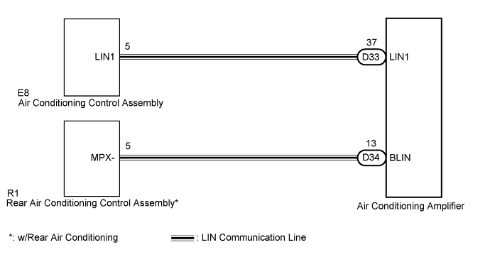
The operation signals of a switch etc. are exchanged between terminal LIN1 of the air conditioning control assembly and terminal LIN1 of the air conditioning amplifier.
WIRING DIAGRAM
INSPECTION PROCEDURE
PROCEDURE
-
CHECK AIR CONDITIONING SYSTEM (OPERATION)
Result Result Proceed to Front air conditioning control malfunctions A Rear air conditioning control malfunctions B
B 
CHECK HARNESS AND CONNECTOR (REAR A/C CONTROL ASSEMBLY - AIR CONDITIONING AMPLIFIER) Click here
A 
-
CHECK HARNESS AND CONNECTOR (A/C CONTROL ASSEMBLY - AIR CONDITIONING AMPLIFIER)
-
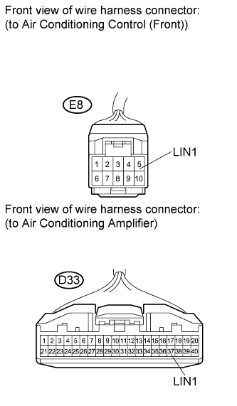
Disconnect the connector from the air conditioning control assembly.
-
Disconnect the connector from the air conditioning amplifier.
-
Measure the resistance according to the value(s) in the table below.
Standard resistance Tester Connection Condition Specified Condition D33-37 (LIN1) - E8-5 (LIN1) Always Below 1 Ω D33-37 (LIN1) - Body ground Always 10 kΩ or higher
NG 
REPAIR OR REPLACE HARNESS OR CONNECTOR
OK 
PROCEED TO NEXT CIRCUIT INSPECTION SHOWN IN PROBLEM SYMPTOMS TABLE Click here
-
-
CHECK HARNESS AND CONNECTOR (REAR A/C CONTROL ASSEMBLY - AIR CONDITIONING AMPLIFIER)
-
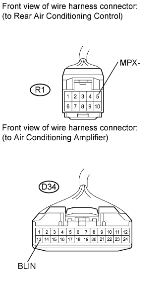
Disconnect the connector from the rear air conditioning control assembly.
-
Disconnect the connector from the air conditioning amplifier.
-
Measure the resistance according to the value(s) in the table below.
Standard resistance Tester Connection Condition Specified Condition D34-13 (BLIN) - R1-5 (MPX-) Always Below 1 Ω D34-13 (BLIN) - Body ground Always 10 kΩ or higher
NG
REPAIR OR REPLACE HARNESS OR CONNECTOR
OK
PROCEED TO NEXT CIRCUIT INSPECTION SHOWN IN PROBLEM SYMPTOMS TABLE Click here
-