AIR CONDITIONING SYSTEM (for Manual Air Conditioning System) Air Conditioning Compressor Magnetic Clutch Circuit
DESCRIPTION
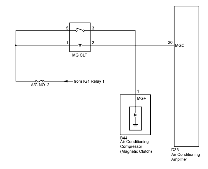
When the air conditioning amplifier is turned on, a magnetic clutch ON signal is sent from the MGC terminal of the air conditioning amplifier. Then, the MGC relay turns on to operate the magnetic clutch.
WIRING DIAGRAM
INSPECTION PROCEDURE
PROCEDURE
-
READ VALUE USING INTELLIGENT TESTER
-
Connect the intelligent tester to the DLC3.
-
Turn the ignition switch on (IG) and turn the intelligent tester main switch on.
-
Turn the A/C switch ON and OFF.
-
Select the item below in the Data List, and read the display on the intelligent tester.
Data List / Engine: Tester Display Measure Item/Range Normal Condition Diagnostic Note A/C Signal
(A/C Signal)
A/C signal / ON or OFF ON: A/C ON
OFF: A/C OFF
- OK The display is as specified in the normal condition column.
NG 
PROCEED TO NEXT CIRCUIT INSPECTION SHOWN IN PROBLEM SYMPTOMS TABLE Click here
OK 
-
-
INSPECT FUSE (A/C NO. 2)
-
Remove the A/C NO. 2 fuse from the instrument panel junction block.
-
Measure the resistance of the fuse.
Standard resistance Tester Connection Condition Specified Condition A/C NO. 2 fuse Always Below 1 Ω
NG
REPLACE FUSE (A/C NO. 2)
OK
-
-
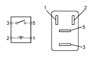
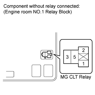
INSPECT MAGNET-CLUTCH RELAY (MG CLT)
-
Remove the MG CLT relay from the engine room No. 1 relay block and junction block.
-
Measure the resistance according to the value(s) in the table below.
Standard resistance Tester Connection Specified Condition 3 - 5 10 kΩ or higher 3 - 5 Below 1 Ω
(when battery voltage is applied to terminals 1 and 2)
NG
REPLACE MAGNET-CLUTCH RELAY (MG CLT)
OK
-
-
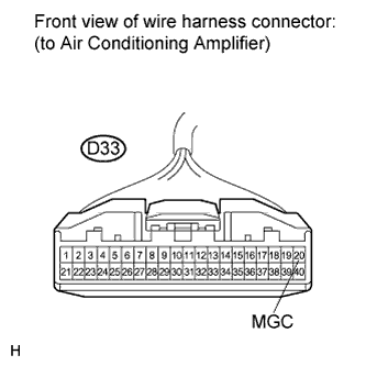
CHECK HARNESS AND CONNECTOR (AIR CONDITIONING AMPLIFIER - BATTERY)
-
Disconnect the connector from the air conditioning amplifier.
-
Measure the voltage according to the value(s) in the table below.
Standard voltage Tester Connection Condition Specified Condition D33-20 (MGC) - Body ground Ignition switch off Below 1 V D33-20 (MGC) - Body ground Ignition switch on (IG) 11 to 14 V
NG
REPAIR OR REPLACE HARNESS OR CONNECTOR (AIR CONDITIONING AMPLIFIER - BATTERY)
OK
-
-
INSPECT AIR CONDITIONING AMPLIFIER
-
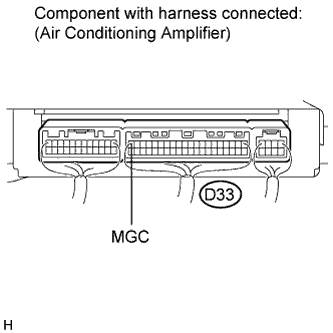
Reconnect the connector to the air conditioning amplifier.
-
Measure the voltage according to the value(s) in the table below.
Standard voltage Tester Connection Condition Specified Condition D33-20 (MGC) - Body ground Ignition switch on (IG)
A/C switch: OFF
11 to 14 V D33-20 (MGC) - Body ground Ignition switch on (IG)
A/C switch: ON
Below 1 V
NG
REPLACE AIR CONDITIONING AMPLIFIER Click here
OK
-
-
INSPECT AIR CONDITIONING COMPRESSOR
-
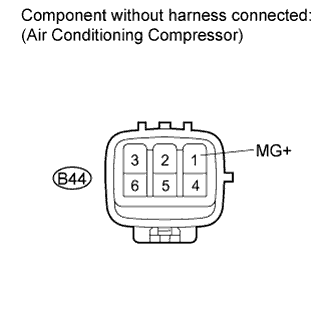
Disconnect the connector from the air conditioning compressor.
-
Measure the resistance of the connector.
-
When connector terminal 1 (MG+) is connected to the positive (+) battery terminal, and the body ground is connected to the negative (-) battery terminal, check that the following occurs: 1) the magnetic clutch's operating sound is emitted, and 2) the magnetic clutch's hub and rotor lock.
Standard resistance Tester Connection Condition Specified Condition B44-1 (MG+) - Body ground Always Below 1 Ω
NG
REPLACE AIR CONDITIONING COMPRESSOR Click here
OK
-
-
CHECK HARNESS AND CONNECTOR (ENGINE ROOM NO. 1 R/B AND J/B - BATTERY)
-
Remove the MG CLT relay from the engine room No. 1 relay block and junction block.
-
Turn the ignition switch on (IG).
-
Measure the voltage according to the value(s) in the table below.
Standard voltage Tester Connection Condition Specified Condition Relay block MG CLT relay terminal 5 - Body ground Always 11 to 14 V Relay block MG CLT relay terminal 1 - Body ground Always 11 to 14 V
NG
REPAIR OR REPLACE HARNESS OR CONNECTOR
OK 
REPAIR OR REPLACE HARNESS OR CONNECTOR
-