AIR CONDITIONING SYSTEM (for Manual Air Conditioning System) Heater Control Panel Power Source Circuit
DESCRIPTION
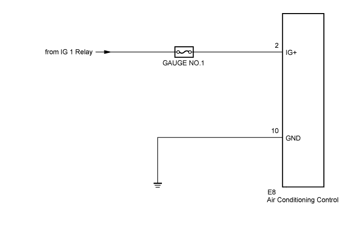
Battery voltage is supplied to the heater control panel (A/C control assembly) through the A/C No. 2 fuse.
WIRING DIAGRAM
INSPECTION PROCEDURE
PROCEDURE
-
CHECK HARNESS AND CONNECTOR (IG+ - BODY GROUND)
-
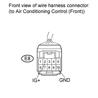
Disconnect the connector from the heater control panel.
-
Measure the voltage according to the value(s) in the table below.
Standard voltage Tester Connection Condition Specified Condition E8-2 (IG+) - Body ground Ignition switch on (IG) 11 to 14 V E8-2 (IG+) - Body ground Ignition switch off Below 1 V Result Result Proceed to OK A NG (without Smart entry and start system) B NG (with Smart entry and start system) C
B 
GO TO STARTING SYSTEM
C
GO TO PUSH BUTTON START SYSTEM
A 
-
-
CHECK HARNESS AND CONNECTOR (GND - BODY GROUND)
-
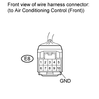
Measure the resistance according to the value(s) in the table below.
Standard resistance Tester Connection Condition Specified Condition E8-10 (GND) - Body ground Always Below 1 Ω
NG
REPAIR OR REPLACE HARNESS OR CONNECTOR
OK 
PROCEED TO NEXT CIRCUIT INSPECTION SHOWN IN PROBLEM SYMPTOMS TABLE
-