| DTC Code | DTC Name |
|---|---|
| Blower Motor Circuit |
DESCRIPTION
The blower motor is operated by signals from the air conditioning amplifier. Blower motor speed signals are transmitted in accordance with changes in the duty ratio.
INSPECTION PROCEDURE
PROCEDURE
- Click here
PERFORM ACTIVE TEST USING INTELLIGENT TESTER (BLOWER MOTOR)
-
Connect the intelligent tester to the DLC3.
-
Turn the ignition switch on (IG) and turn the intelligent tester main switch on.
-
Select the item below in the Active Test, and then check that the blower motor operates.
Table 1. Active Test / Air Conditioner: Tester Display Test Part Control Range Diagnostic Note Blower Motor Blower motor Min.: 0, Max.: 31 - Result Result Proceed to NG (blower motor does not operate) A NG (blower motor operates but does not change speed) B OK C
-
- Click here
INSPECT FUSE (HTR-H)
-
Remove the HTR H-fuse from the main body ECU.
-
Measure the resistance according to the value(s) in the table below.
Standard resistance Tester Connection Condition Specified Condition HTR H-fuse Always Below 1Ω
- OKClick here
- NGClick here
-
- Click here
CHECK HARNESS AND CONNECTOR (BLOWER MOTOR - BODY GROUND)
-
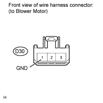
Disconnect the D30 motor connector.
-
Measure the resistance according to the value(s) in the table below.
Standard resistance Tester Connection Condition Specified Condition D30-1 (GND) - Body ground Always Below 1 Ω
- OKClick here
- NGClick here
-
- Click here
CHECK HARNESS AND CONNECTOR (BLOWER MOTOR - BATTERY)
-
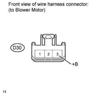
Disconnect the D30 motor connector.
-
Measure the voltage according to the value(s) in the table below.
Standard voltage Tester Connection Condition Specified Condition D30-3 (+B) - Body ground Ignition switch on (IG) 11 to 14 V
- OKClick here
- NGClick here
-
- Click here
CHECK HARNESS AND CONNECTOR (AIR CONDITIONING AMPLIFIER - BODY GROUND)
-
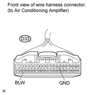
Disconnect the D33 amplifier connector.
-
Measure the voltage according to the value(s) in the table below.
Standard voltage Tester Connection Condition Specified Condition D33-23 (BLW) - D33-14 (GND) Ignition switch on (IG)
Blower switch OFF
4.5 to 5.5 V
- OKClick here
- NGClick here
-
- Click here
CHECK AIR CONDITIONING AMPLIFIER
-
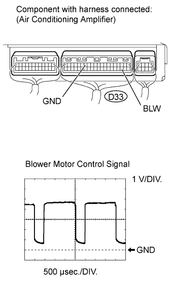
Remove the air conditioning amplifier with its connectors still connected.
-
Check the waveform of the amplifier connector.
OK Waveform is as shown in the illustration. Tip:The waveform varies with the blower level.
Item Content Tester Connection D33-23 (BLW) - D33-14 (GND) Tool Setting 1 V/DIV., 500 μsec./DIV. Condition Ignition switch on (IG)
Blower switch LO
- OKClick here
- NGClick here
-
- Click here
REPLACE BLOWER W/ FAN MOTOR SUB-ASSEMBLYClick here
- Click here
PROCEED TO NEXT CIRCUIT INSPECTION SHOWN IN PROBLEM SYMPTOMS TABLEClick here
- Click here
REPLACE FUSE
- Click here
REPAIR OR REPLACE HARNESS OR CONNECTOR
- Click here
REPLACE AIR CONDITIONING AMPLIFIERClick here