CAN COMMUNICATION SYSTEM Open in One Side of CAN Sub Bus Line
DESCRIPTION
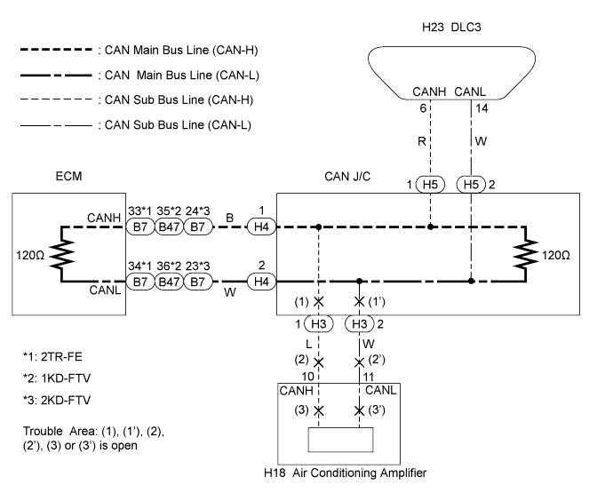
If "Engine", "ECT (*1)" and "Air Conditioner" do not appear on the intelligent tester's "Communication Bus Check" screen, one side of CAN sub bus line may be open (either CAN-H or CAN-L of the CAN sub bus lines) or the ECM may be defective.
| Symptom | Trouble Area |
|---|---|
| "Engine", "ECT (*1)" and "Air Conditioner" do not appear on the intelligent tester's "Communication Bus Check" screen. |
|
Tech Tips
*1: Applicable only to automatic transmission vehicles with 1KD-FTV or 2KD-FTV engine.
WIRING DIAGRAM
INSPECTION PROCEDURE
PROCEDURE
-
CHECK FOR AN OPEN IN ONE SIDE OF THE CAN SUB BUS LINE (AIR CONDITIONING AMPLIFIER SUB BUS LINE)
-
Turn the ignition switch off.
-
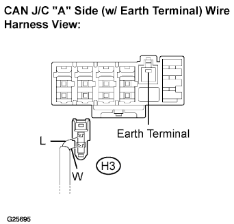
Disconnect the air conditioning amplifier sub bus line connector (H3) from the CAN J/C.
Note
-
Before disconnecting the connector, make a note of where it is connected.
-
Reconnect the connector to its original position.
-
-
Turn the ignition switch on.
-
Select "Communication Bus Check"on the intelligent tester. Click here
Result Go to step Result A "Engine", "ECT (*1)" and "A/C" are not displayed. B "A/C" is not displayed ("Engine" and "ECT (*1)"are displayed). Tech Tips
*1: Applicable only to automatic transmission vehicles with 1KD-FTV or 2KD-FTV engine.
B 
CONNECT CONNECTOR Click here
A 
-
-
INSPECT CAN J/C
-
Turn the ignition switch off.
-
Disconnect the all connectors (H3), (H4) and (H5) from the CAN J/C.
Note
-
Before disconnecting the connectors, make a note of where it is connected.
-
Reconnect the connectors to its original position.
-
-
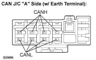
Measure the resistance according to the value(s) in the table below.
Standard resistance Tester Connection Condition Specified value CANH - CANL IG switch OFF 108 to 132 Ω
NG 
REPLACE CAN J/C
OK 
REPLACE ECM
-
-
CONNECT CONNECTOR
-
Reconnect the air conditioning amplifier sub bus line connector (H3) to the CAN J/C.
NEXT
-
-
CHECK FOR AN OPEN IN ONE SIDE OF THE CAN SUB BUS LINE (AIR CONDITIONING AMPLIFIER SUB BUS LINE)
-
Turn the ignition switch off.
-
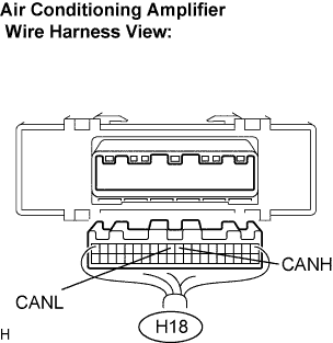
Disconnect the air conditioning amplifier connector (H18).
-
Measure the resistance according to the value(s) in the table below.
Standard resistance Tester Connection Condition Specified Value H18-10 (CANH) -
H18-11 (CANL)
IG switch OFF 54 to 69 Ω
NG
REPAIR OR REPLACE AIR CONDITIONING AMPLIFIER SUB BUS LINE OR CONNECTOR
OK
REPLACE AIR CONDITIONING AMPLIFIER
-