CAN COMMUNICATION SYSTEM CAN Bus Line
DESCRIPTION
Measure the resistance from the DLC3 before checking the CAN bus lines to troubleshoot the CAN communication system.
WIRING DIAGRAM

INSPECTION PROCEDURE
PROCEDURE
-
CHECK CAN BUS WIRE (MAIN BUS LINE FOR DISCONNECTION, BUS LINES FOR SHORT CIRCUIT)
-
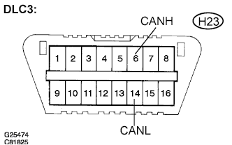
Measure the resistance according to the value(s) in the table below.
Standard resistance Tester Connection Condition Specified Value Result H23-6 (CANH) - H23-14 (CANL) IG switch OFF 54 to 69 Ω OK H23-6 (CANH) - H23-14 (CANL) IG switch OFF 69 Ω or higher NG - A H23-6 (CANH) - H23-14 (CANL) IG switch OFF Below 54 Ω NG - B
NG-A 
OPEN IN CAN MAIN BUS LINE
NG-B
SHORT IN CAN BUS LINES
OK 
-
-
CHECK CAN BUS LINE FOR SHORT TO B+
-
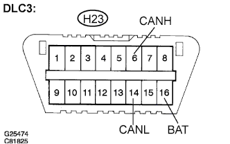
Measure the resistance according to the value(s) in the table below.
Standard resistance Tester Connection Condition Specified Value H23-6 (CANH) - H23-16 (BAT) IG switch OFF 1 MΩ or higher H23-14 (CANL) -
H23-16 (BAT)
IG switch OFF 1 MΩ or higher Tech Tips
NG: Short to B+ in CAN Bus Line Click here
NG
SHORT TO B+ IN CAN BUS LINE
OK
-
-
CHECK CAN BUS LINE FOR SHORT TO GND
-

Measure the resistance according to the value(s) in the table below.
Standard resistance Tester Connection Condition Specified Value H23-4 (CG) - H23-6 (CANH) IG switch OFF 3 kΩ or higher H23-4 (CG) - H23-14 (CANL) IG switch OFF 3 kΩ or higher Tech Tips
-
OK: HOW TO PROCEED WITH TROUBLESHOOTING Click here
-
NG: Short to GND in CAN Bus Line Click here
-
NG
SHORT TO GND IN CAN BUS LINE
OK 
GO TO "HOW TO PROCEED WITH TROUBLESHOOTING"
-