CAN COMMUNICATION SYSTEM Combination Meter ECU Communication Stop Mode
DESCRIPTION
| Detection Item | Symptom | Trouble Area |
|---|---|---|
| Combination Meter ECU Communication Stop Mode | Either condition is met:
|
|
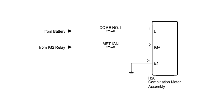
WIRING DIAGRAM
INSPECTION PROCEDURE
Note
Inspect the fuses for circuits related to this system before performing the following inspection procedure.
PROCEDURE
-
CHECK HARNESS AND CONNECTOR (COMBINATION METER ASSEMBLY - BATTERY AND BODY GROUND)
-
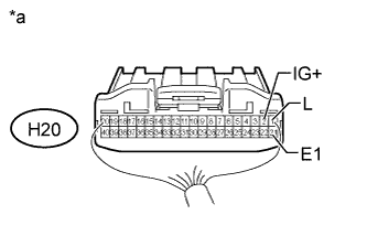
Text in Illustration *a Rear view of wire harness connector
(to Combination Meter Assembly)
Disconnect the combination meter assembly connector.
-
Measure the resistance according to the value(s) in the table below.
Standard Resistance Tester Connection Condition Specified Condition H20-21 (E1) - Body ground Always Below 1 Ω -
Measure the voltage according to the value(s) in the table below.
Standard Voltage Tester Connection Condition Specified Condition H20-1 (L) - Body ground Always 11 to 14 V H20-2 (IG+) - Body ground Ignition switch ON 11 to 14 V
NG 
REPAIR OR REPLACE HARNESS OR CONNECTOR
OK 
REPLACE COMBINATION METER ASSEMBLY Click here
-