LIN COMMUNICATION SYSTEM TERMINALS OF ECU

-
CHECK CERTIFICATION ECU (SMART KEY ECU ASSEMBLY)
-
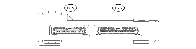
Disconnect the B75 certification ECU connector.
-
Measure the resistance and voltage according to the value(s) in the table below.
Terminal No. (Symbol) Wiring Color Terminal Description Condition Specified Condition B75-10 (E) - Body ground W-B - Body ground Ground Always Below 1 Ω B75-1 (+B) - B75-10 (E) L - W-B Battery power supply Always 11 to 14 V If the result is not as specified, there may be a malfunction on the wire harness side.
-
-
CHECK ID CODE BOX (IMMOBILISER CODE ECU)
-
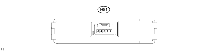
Disconnect the H81 ID code box connector.
-
Measure the resistance and voltage according to the value(s) in the table below.
Terminal No. (Symbol) Wiring Color Terminal Description Condition Specified Condition H81-5 (GND) - Body ground W-B - Body ground Ground Always Below 1 Ω H81-1 (+B) - H81-5 (GND) W - W-B Battery power supply Always 11 to 14 V If the result is not as specified, there may be a malfunction on the wire harness side.
-
-
CHECK STEERING LOCK ACTUATOR ASSEMBLY

-
Disconnect the H80 steering lock actuator assembly connector.
-
Measure the resistance and voltage according to the value(s) in the table below.
Terminal No. (Symbol) Wiring Color Terminal Description Condition Specified Condition H80-1 (GND) - Body ground W-B - Body ground Ground Always Below 1 Ω H80-6 (IG2) - H80-1 (GND) B - W-B IG signal Engine switch off Below 1 V Engine switch on (IG) 11 to 14 V H80-7 (B) - H80-1 (GND) W - W-B Battery power supply Always 11 to 14 V If the result is not as specified, there may be a malfunction on the wire harness side.
-