CAN COMMUNICATION SYSTEM TERMINALS OF ECU

Tech Tips
This section describes the standard CAN values for all CAN related components.
-
CAN J/C
-
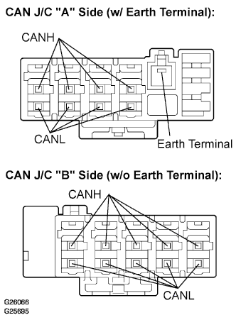
CAN J/C connectors.
Tech Tips
-
The connectors connected to the CAN J/C can be distinguished by the colors of the bus lines and the connecting side of the connector.
-
H3, H4 and H5 are interchangeable.
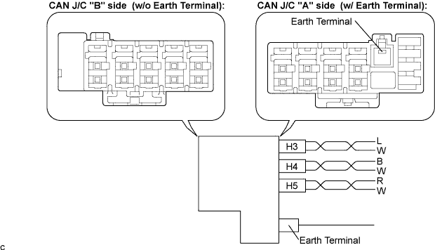
CAN J/C connectors ("A" side, w/ earth terminal) Color (CAN-H Side) Color (CAN-L Side) Air conditioning amplifier (H3) L W ECM (H4) B W DLC3 (H5) R W -
-
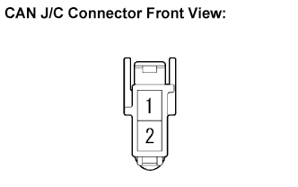
The terminals of the CAN J/C connectors.
Terminal Terminal symbol 1 CANH 2 CANL -
Measure the resistance according to the value(s) in the table below.
-
-
DLC3
-
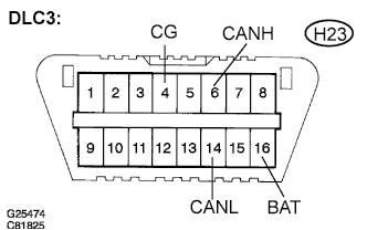
Check the DLC3.
-
Measure the resistance according to the value(s) in the table below.
-
-
-
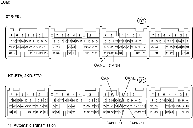
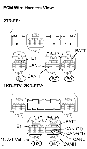
ECM (2TR-FE, 1KD-FTV, 2KD-FTV)
-
Measure the resistance according to the value(s) in the table below.
-
Measure the resistance according to the value(s) in the table below.
-
-
AIR CONDITIONING AMPLIFIER
-
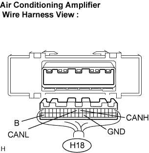
Check the harness side connector (H18) of the air conditioning amplifier.
-
Disconnect the connector (H18) from the air conditioning amplifier.
-
Measure the resistance according to the value(s) in the table below.
-
-
-
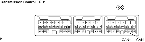
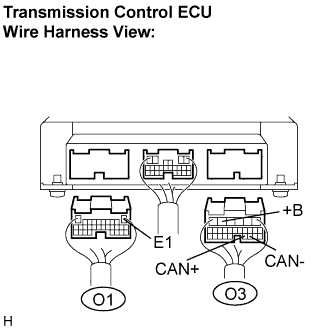
TRANSMISSION CONTROL ECU (*2)
Tech Tips
*2: Applicable only to automatic transmission vehicles with 1KD-FTV or 2KD-FTV engine.
-
Measure the resistance according to the value(s) in the table below.
-
Measure the resistance according to the value(s) in the table below.
-