CAN COMMUNICATION SYSTEM DIAGNOSIS SYSTEM

-
BUS CHECK (COMMUNICATION MALFUNCTION ECU)
Only CAN communication system DTCs for each ECU can be output to the intelligent tester.
-
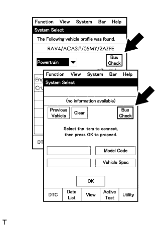
Select "Bus Check" from the "System Select" screen on the intelligent tester.
-
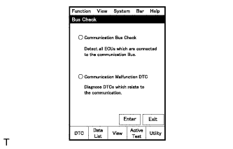
Select "Communication Malfunction DTC" from the "Bus Check" screen, and then select "Enter".
-
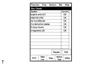
Select the system of the DTC to be checked and select "Details".
-
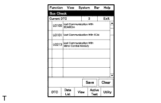
CAN communication system DTCs are output.
-
-
BUS CHECK (COMMUNICATION BUS CHECK)
Tech Tips
The ECUs and sensors that are properly connected to the CAN communication system can be displayed using the intelligent tester.
-
Select "Communication Bus Check" from the "Bus Check" screen.
-
The screen displays the ECUs and sensors that are properly connected to the CAN communication system.
Tech Tips
-
If any properly connected ECUs or sensors are not displayed, there is a communication stop in the system Click here.
-
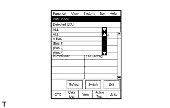
The default item displayed in the combo box is "ALL". When checking the ECUs (sensors) connected to each bus, pull down the combo box and select the bus to be checked from the drop-down list. The drop-down list displays "ALL", "V Bus" and the names of the remaining buses.
Combo Box Display Content ALL All ECUs (sensors) connected to the CAN bus V Bus ECUs (sensors) connected to the V Bus Bus Name ECUs (sensors) connected to the selected bus -
The connection status (shown below) is indicated by the background color displayed behind the system name.
ECU (Sensor) on V Bus Background Color Connection Status White Detected normally Yellow Could not be detected in the past, but is currently detected Red Detected in the past, but cannot be detected now Yellow Could not be detected in the past, but is currently detected Not displayed Has never been detected ECU (Sensor) with no Data Monitor History Background Color Connection Status White Detected normally Yellow Could not be detected in the past, but is currently detected Red Detected in the past, but cannot be detected now Not displayed Has never been detected ECU (Sensor) with Data Monitor History Background Color Connection Status White Detected normally Yellow Could not be detected in the past, but is currently detected Red Detected in the past, but cannot be detected now Red Has never been detected but has connection history Not displayed Has never been detected and has no connection history
-
-
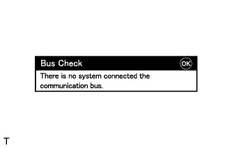
"There is no system connected the communication bus." is displayed if there are no ECUs or sensors connected to the CAN bus.
-
-
CHECK INSTALLED SYSTEMS (ECUS AND SENSORS) THAT USE CAN COMMUNICATION
-
Systems (ECUs and sensors) that use CAN communication vary depending on the optional settings of the vehicle. Check which systems (ECUs and sensors) are installed on the vehicle.
ECU/Sensor Name Tester Display Installed on ECM ECM (Engine) All vehicles Combination meter assembly Combination Meter All vehicles Air conditioning amplifier assembly Air Conditioning Amplifier For vehicles with an air conditioning system, except 5L-E Certification ECU (smart key ECU assembly) Certification (Smart) For vehicles with a smart entry and start system Headlight leveling ECU assembly Headlight swivel (AFS) For vehicles with an LED headlight
-
-
DTC TABLE BY ECU
Tech Tips
-
In the CAN communication system, CAN communication system DTCs stored by an ECU can be output by using the intelligent tester.
-
If CAN communication system DTCs are output, the trouble cannot be determined solely from the DTCs. Perform troubleshooting according to "How to Proceed with Troubleshooting" Click here.
-
ECM
Tech Tips
DTC communication uses the CAN communication system.
DTC Code Detection Item U0101* Lost Communication with TCM
-
*: Refer to ECD System
-
for 1KD-FTV (w/ DPF): Click here
-
for 1KD-FTV (w/o DPF): Click here
-
for 2KD-FTV : Click here
-
-
TRANSMISSION CONTROL ECU ASSEMBLY (for 1KD-FTV, 2KD-FTV and Automatic Transmission)
Tech Tips
DTC communication uses the CAN communication system.
DTC Code Detection Item U0100* Lost Communication with ECM/PCM "A"
-
*: Refer to Electronic Controlled Automatic Transmission System Click here.
-
-
AIR CONDITIONING AMPLIFIER ASSEMBLY (w/ Air Conditioning System, except 5L-E)
Tech Tips
DTC communication uses the CAN communication system.
DTC Code Detection Item B1499 Communication Malfunction (Engine&Meter ECU) -
COMBINATION METER ASSEMBLY
Tech Tips
DTC communication uses the CAN communication system.
DTC Code Detection Item U0100 Lost Communication with ECM/PCM "A" U0182 Lost Communication with Lighting Control Module Front -
CERTIFICATION ECU (SMART KEY ECU ASSEMBLY) (w/ Smart Entry and Start System)
Tech Tips
DTC communication uses the CAN communication system.
DTC Code Detection Item U0100 Lost Communication With ECM/PCM "A" U0155 Lost Communication with Instrument Panel Cluster (IPC) Control Module -
HEADLIGHT LEVELING ECU ASSEMBLY (for LED Headlight)
DTC Code Detection Item U0100 Lost Communication with ECM/PCM "A" U0155 Lost Communication with Instrument Panel Cluster (IPC) Control Module U1000* CAN Communication Failure(Message Registry)
-
*: Refer to Lighting System Click here.
-
-
-
DTC COMBINATION TABLE
-
○: Stored.
-
X: When one side of branch wire is open, storage may occur.
-
-: Not stored.
Output from Output DTC Detection Item Detected Communication Stop Mode V1 Bus ECM Communication Stop Mode Air Conditioning Amplifier Communication Stop Mode Combination Meter ECU Communication Stop Mode Certification ECU Communication Stop Mode AFS ECU Communication Stop Mode Air conditioning amplifier assembly B1499 Communication Malfunction (Engine&Meter ECU) ○ ○ ○ X X Combination meter assembly U0100 Lost Communication with ECM/PCM "A" ○ X ○ X X U0182 Lost Communication with Lighting Control Module Front X X ○ X ○ Certification ECU (smart key ECU assembly) U0100 Lost Communication With ECM/PCM "A" ○ X X ○ X U0155 Lost Communication with Instrument Panel Cluster (IPC) Control Module X X ○ ○ X Headlight leveling ECU assembly U0100 Lost Communication with ECM/PCM "A" ○ X X X ○ U0155 Lost Communication with Instrument Panel Cluster (IPC) Control Module X X ○ X ○
-