SLIDE DOOR CLOSER SYSTEM Door Control Relay Power source Circuit
DESCRIPTION
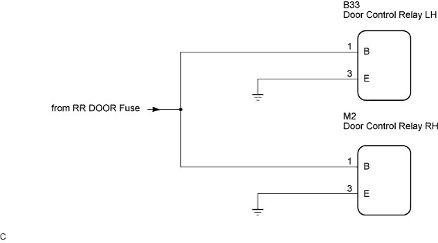
Power is supplied from the RR DOOR fuse to the door control relay. In order to operate the slide door closer relay.
WIRING DIAGRAM
INSPECTION PROCEDURE
PROCEDURE
-
CHECK WIRE HARNESS (DOOR CONTROL RELAY - BATTERY AND BODY GROUND)
-
Disconnect the door control relay.
-
Measure the resistance according to the value(s) in the table below.
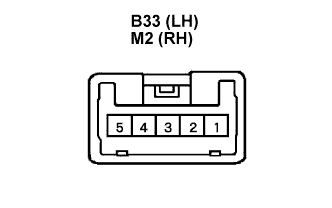
Standard resistance LH side Tester Connection Condition Specified Condition B33-3 - Body ground Always Below 1 Ω RH side Tester Connection Condition Specified Condition M2-3 - Body ground Always Below 1 Ω -
Measure the voltage according to the value(s) in the table below.
Standard voltage LH side Tester Connection Condition Specified Condition B33-1 - Body ground Always 10 to 14 V RH side Tester Connection Condition Specified Condition M2-1 - Body ground Always 10 to 14 V
NG 
REPAIR OR REPLACE HARNESS OR CONNECTOR
OK 
PROBLEM TO NEXT CIRCUIT INSPECTION SHOWN IN PROBLEM SYMPTOMS TABLE
-