SLIDE DOOR CLOSER SYSTEM Slide Door Closer Motor LH Circuit
DESCRIPTION
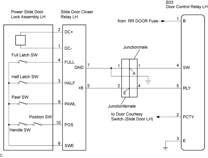
The slide door closer relay controls the power slide door lock assembly. In response to the output signals from the switches in the power slide door lock assembly, the slide door closer drives the closer motor.
WIRING DIAGRAM
INSPECTION PROCEDURE
PROCEDURE
-
INSPECT POWER SLIDE DOOR LOCK ASSEMBLY LH
-
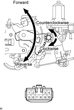
Inspect the slide door closer motor.
-
Apply battery voltage and check operation of the slide door closer motor.
Standard Measurement Condition Specified Condition Battery positive (+) → Terminal 2
Battery negative (-) → Terminal 1
Close (Forward) Battery positive (+) → Terminal 1
Battery negative (-) → Terminal 2
Open (Reverse)
-
-
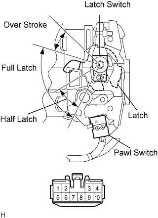
Inspect the pawl switch and latch switch.
-
Measure the resistance when the switch is operated according to the value(s) in the table below.
Standard resistance Pawl switch Tester Connection Condition Specified Condition 8 - 9
-
Open
-
Half latch
-
Full latch
10 kΩ or higher 8 - 9 Unlatched Below 1 Ω Latch switch Tester Connection Condition Specified Condition 3 - 4, 4- 8 Open Below 1 Ω 4 - 8 Half latch Below 1 Ω 3 - 4, 4- 8 Full latch 10 kΩ or higher - Over stroke 10 kΩ or higher -
-
-
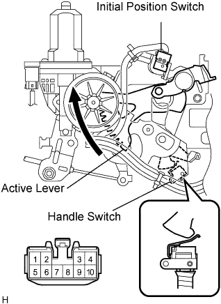
Inspect the the initial position switch and handle switch.
-
Measure the resistance when the switch is operated according to the value(s) in the table below.
Standard resistance Tester Connection Condition Specified Condition 8 - 10
-
Handle switch ON (Handle initial position)
-
Initial position switch OFF (Active lever initial position)
10 kΩ or higher 8 - 10
-
Handle switch OFF (As handling)
-
Initial position switch OFF (Active lever initial position)
10 kΩ or higher 8 - 10
-
Handle switch ON (Handle initial position)
-
Initial position switch ON (As closer operating)
Below 1 Ω 8 - 10
-
Handle switch OFF (As handling)
-
Initial position switch ON (As closer operating)
10 kΩ or higher -
-
NG 
REPLACE POWER SLIDE DOOR LOCK ASSEMBLY LH
OK 
-
-
INSPECT SLIDE DOOR CONTROL JUNCTIONFEMALE
-
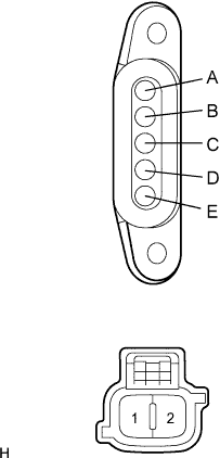
Inspect the slide door control junctionfemale.
-
Measure the resistance when the switch is operated according to the value(s) in the table below.
Standard resistance Tester Connection Condition Specified Condition A - 1 Always Below 1 Ω E - 2 Always Below 1 Ω
NG
REPLACE SLIDE DOOR CONTROL JUNCTIONFEMALE
OK
-
-
INSPECT SLIDE DOOR CONTROL JUNCTIONMALE
-
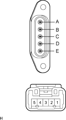
Inspect the slide door control junctionmale.
-
Measure the resistance when the switch is operated according to the value(s) in the table below.
Standard resistance Tester Connection Condition Specified Condition A - 1 Always Below 1 Ω E - 4 Always Below 1 Ω
NG
REPLACE SLIDE DOOR CONTROL JUNCTIONMALE
OK
-
-
CHECK WIRE HARNESS (SLIDE DOOR CLOSER RELAY LH - DOOR CONTROL RELAY LH)
-
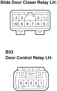
Disconnect the B33 and slide door closer relay connectors.
-
Measure the resistance according to the value(s) in the table below.
Standard resistance Tester Connection Condition Specified Condition B33-4 (SW) - 7 (GND) Slide door CLOSE Below 1 Ω B33-5 (RLY) - 5 (+B) Slide door CLOSE Below 1 Ω B33-4 (SW) - Body ground Slide door OPEN 10 kΩ or higher B33-5 (RLY) - Body ground Slide door OPEN 10 kΩ or higher
NG
REPAIR OR REPLACE HARNESS OR CONNECTOR
OK 
PROCEED TO NEXT CIRCUIT INSPECTION SHOWN IN PROBLEM SYMPTOMS TABLE
-