POWER SLIDE DOOR SYSTEM Power Slide Door RH does not Operate When Using Inside / Outside Handle
DESCRIPTION
The door control relay assembly controls the power slide door and activates the slide door motor unit RH. When the door handle is pulled, the power slide door automatically moves to the fully open position.
WIRING DIAGRAM
INSPECTION PROCEDURE
PROCEDURE
-
INSPECT SLIDE DOOR LOCK REMOTE CONTROL ASSEMBLY RH
-
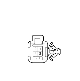
Remove the slide door lock remote control assembly Click here.
-
Measure the resistance according to the value(s) in the table below.
Standard Resistance Tester Connection Handle Condition Specified Condition 1 - 3 Handle in initial position 10 kΩ or higher 2 - 3 1 - 3 Handle pulled Below 1 Ω 2 - 3
NG 
REPLACE SLIDE DOOR LOCK REMOTE CONTROL ASSEMBLY RH Click here
OK 
-
-
INSPECT REAR DOOR WIRE RH
-
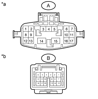
Text in Illustration *a Rear Door Wire RH
(Door Control Relay Assembly Side)
*b Rear Door Wire RH
(Slide Door Lock Remote Control Assembly RH Side)
Disconnect the ci1 and fc1 rear door wire RH connectors.
-
Measure the resistance according to the value(s) in the table below.
Standard Resistance Tester Connection Condition Specified Condition A-8 - B-11 Always Below 1 Ω A-12 - B-17 Always Below 1 Ω A-10 - B-16 Always Below 1 Ω
NG
REPLACE REAR DOOR WIRE RH Click here
OK
-
-
CHECK HARNESS AND CONNECTOR (SLIDE DOOR LOCK REMOTE CONTROL RH - DOOR CONTROL RELAY ASSEMBLY)
-
Disconnect the f4 slide door lock remote control RH connector.
-
Disconnect the I4 door control relay assembly connector.
-
Measure the resistance according to the value(s) in the table below.
Standard Resistance Tester Connection Condition Specified Condition f4-2 - I4-20 (MPX2) Always Below 1 Ω f4-1 - I4-8 (MPX1) Always Below 1 Ω f4-3 - I4-13 (OSG) Always Below 1 Ω f4-2 or I4-20 (MPX2) - Body ground Always 10 kΩ or higher f4-1 or I4-8 (MPX1) - Body ground Always 10 kΩ or higher f4-3 or I4-13 (OSG) - Body ground Always 10 kΩ or higher
NG
REPAIR OR REPLACE HARNESS OR CONNECTOR
OK 
REPLACE DOOR CONTROL RELAY ASSEMBLY Click here
-