POWER SLIDE DOOR SYSTEM Power Slide Door LH does not Operate When Satellite Switch is Pressed
DESCRIPTION
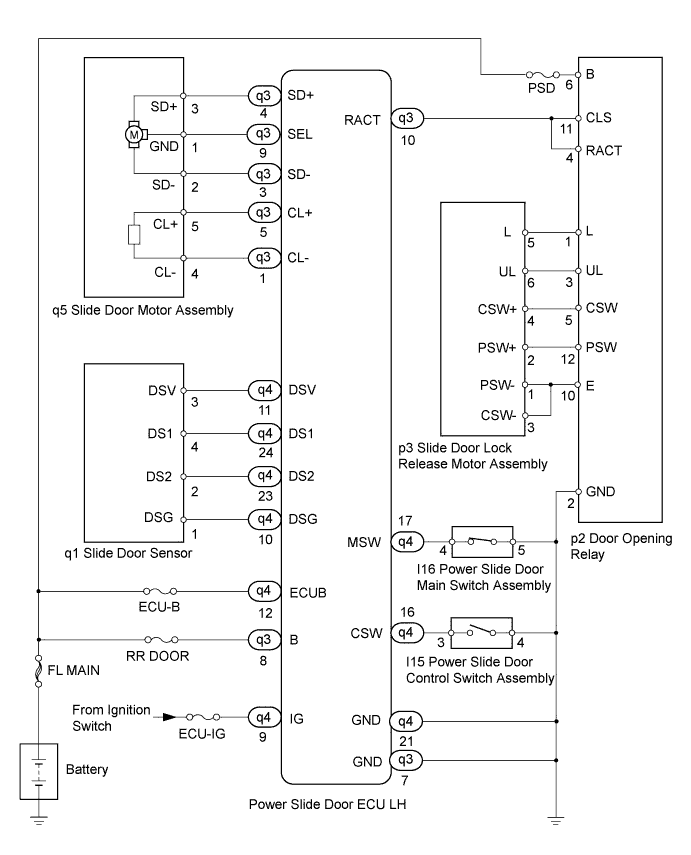
The power slide door ECU LH controls the power slide door and activates the slide motor.
Tech Tips
Before using this flowchart, perform the self-diagnostic mode inspection Click here and make sure no code is output.
WIRING DIAGRAM
INSPECTION PROCEDURE
PROCEDURE
-
CHECK BASIC FUNCTIONS
-
When the engine is running, (1) to (5) are required for the power slide door to operate.
-
The battery voltage is 11 V or more.
-
The vehicle's speed is less than 3 km/h (1 mph) and the shift lever is moved to the P position.
-
The auto slide door main switch is turned ON (the button is not pushed).
-
The slide door is unlocked (the position switch is ON).
-
An open circuit in the power slide door touch sensor is not detected.
-
-
When the engine is not running, (1) to (4) are required for the power slide door to operate.
-
The battery voltage is 11 V or more.
-
The auto slide door main switch is turned ON (the button is not pushed).
-
The slide door is unlocked (the position switch is ON).
-
An open circuit in the power slide door touch sensor is not detected.
Tech Tips
-
For the inside handle, the power slide door can operate only when the child lock is OFF.
-
For the outside handle, the power slide door can operate even when the child lock is ON.
-
-
-
Check that the power slide door malfunctions.
Result Result Proceed to Nothing operates or moves A Motor is emitting sounds but slide door does not move
(lock is released but door does not open)
B
B 
INSPECT SLIDE DOOR MOTOR ASSEMBLY Click here
A 
-
-
INSPECT POWER SLIDE DOOR ECU LH (POWER SOURCE)
-
Disconnect the q3 and q4 connectors from the power slide door ECU LH.
-
Measure the voltage.
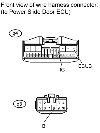
Standard voltage Tester Connection Condition Specified Condition q3-8 (B) - Body ground Always 11 to 14 V q4-9 (IG) - Body ground Ignition switch on 11 to 14 V q4-12 (ECUB) - Body ground Always 11 to 14 V
NG 
REPAIR OR REPLACE POWER SOURCE CIRCUIT
OK
-
-
INSPECT POWER SLIDE DOOR ECU LH (GROUND)
-
Measure the resistance.
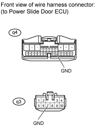
Standard resistance Tester Connection Condition Specified Condition q3-7 (GND) - Body ground Always Below 1 Ω q4-21 (GND) - Body ground Always Below 1 Ω
NG
REPAIR OR REPLACE GROUND CIRCUIT
OK
-
-
INSPECT POWER SLIDE DOOR ECU LH (AUTO SLIDE DOOR CONTROL SWITCH ASSEMBLY CIRCUIT)
-
Measure the resistance.
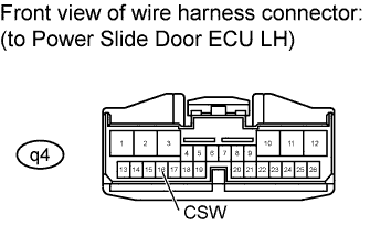
Standard resistance Tester Connection Switch Condition Specified Condition q4-16 (CSW) - Body ground Auto slide door control switch assembly
1: Not pushed →
2: Pushed
1: 10 kΩ or higher →
2: Below 1 Ω
NG
INSPECT AUTO SLIDE DOOR CONTROL SWITCH ASSEMBLY Click here
OK
-
-
INSPECT POWER SLIDE DOOR ECU LH (AUTO SLIDE DOOR MAIN SWITCH ASSEMBLY CIRCUIT)
-
Measure the resistance.
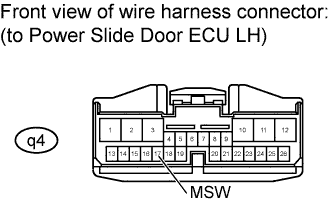
Standard resistance Tester Connection Switch Condition Specified Condition q4-17 (MSW) - Body ground Auto slide door main switch assembly
1: Not pushed →
2: Pushed
1: Below 1 Ω →
2: 10 k Ω or higher
NG
INSPECT AUTO SLIDE DOOR MAIN SWITCH ASSEMBLY Click here
OK
-
-
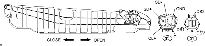
INSPECT SLIDE DOOR MOTOR ASSEMBLY
-
Disconnect the q1 and q5 connectors from the slide door motor assembly.
-
Apply battery voltage to the motor and check operation of the motor.
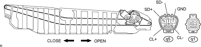
OK Measurement Condition Specified Condition Battery positive (+) → q5-3 (SD+)
Battery negative (-) → q5-1 (GND)
High-speed open operation (clockwise) Battery positive (+) → q5-2 (SD-)
Battery negative (-) → q5-1 (GND)
Low-speed open operation (clockwise) Battery positive (+) → q5-1 (GND)
Battery negative (-) → q5-3 (SD+)
High-speed close operation (counterclockwise) Battery positive (+) → q5-1 (GND)
Battery negative (-) → q5-2 (SD-)
Low-speed close operation (counterclockwise) -
Measure the resistance of the motor clutch.
Standard resistance Tester Connection Specified Condition q5-4 (CL-) - q5-5 (CL+) Below 3.6 Ω
NG
REPLACE SLIDE DOOR MOTOR ASSEMBLY
OK
-
-
CHECK HARNESS AND CONNECTOR (POWER SLIDE DOOR ECU LH - SLIDE DOOR MOTOR ASSEMBLY)
-
Measure the resistance.
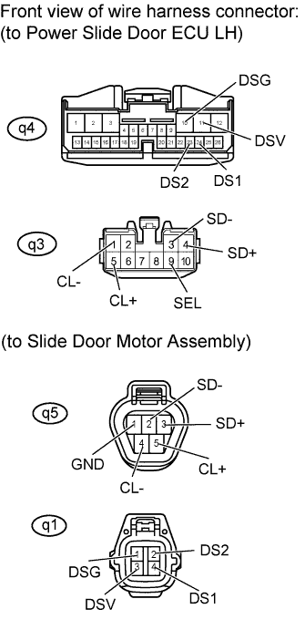
Standard resistance Tester Connection Specified Condition q3-1 (CL-) - q5-4 (CL-) Below 1 Ω q3-3 (SD-) - q5-2 (SD-) Below 1 Ω q3-4 (SD+) - q5-3 (SD+) Below 1 Ω q3-5 (CL+) - q5-5 (CL+) Below 1 Ω q3-9 (SEL) - q5-1 (GND) Below 1 Ω q4-10 (DSG) - q1-1 (DSG) Below 1 Ω q4-11 (DSV) - q1-3 (DSV) Below 1 Ω q4-23 (DS2) - q1-2 (DS2) Below 1 Ω q4-24 (DS1) - q1-4 (DS1) Below 1 Ω -
Reconnect the q1 and q5 connectors to the slide door motor assembly.
NG
REPAIR OR REPLACE HARNESS OR CONNECTOR
OK
-
-
INSPECT SLIDE DOOR LOCK RELEASE MOTOR ASSEMBLY LH
-
Disconnect the p3 connector from the slide door lock release motor assembly LH.
-
Remove the slide door lock release motor assembly LH.
-
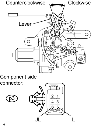
Apply battery voltage to the motor and check operation of the motor.
Standard Measurement Condition Specified Condition Battery positive (+) → p3-6 (UL)
Battery negative (-) → p3-5 (L)
Moves clockwise Battery positive (+) → p3-5 (L)
Battery negative (-) → p3-6 (UL)
Moves counterclockwise
NG
REPLACE SLIDE DOOR LOCK RELEASE MOTOR ASSEMBLY LH
OK
-
-
CHECK HARNESS AND CONNECTOR (SLIDE DOOR LOCK RELEASE MOTOR ASSEMBLY - DOOR OPENING RELAY)
-
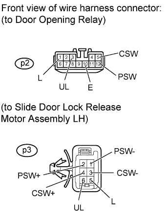
Disconnect the p2 connector from the door opening relay.
-
Measure the resistance.
Standard resistance Tester Connection Specified Condition p2-1 (L) - p3-5 (L) Below 1 Ω p2-3 (UL) - p3-6 (UL) Below 1 Ω p2-5 (CSW) - p3-4 (CSW+) Below 1 Ω p2-12 (PSW) - p3-2 (PSW+) Below 1 Ω p2-10 (E) - p3-3 (CSW-) Below 1 Ω p2-10 (E) - p3-1 (PSW-) Below 1 Ω -
Reconnect the p3 connector to the slide door lock release motor assembly LH.
NG
REPAIR OR REPLACE HARNESS OR CONNECTOR
OK
-
-
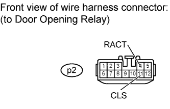
CHECK HARNESS AND CONNECTOR (POWER SLIDE DOOR ECU LH - DOOR OPENING RELAY)
-
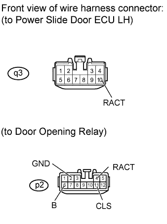
Measure the voltage and resistance.
Standard Tester Connection Condition Specified Condition q3-10 (RACT) - p2-4 (RACT) Always Below 1 Ω q3-10 (RACT) - p2-11 (CLS) Always Below 1 Ω p2-6 (B) - Body ground Always 11 to 14 V p2-2 (GND) - Body ground Always Below 1 Ω
NG
REPAIR OR REPLACE HARNESS OR CONNECTOR
OK
-
-
INSPECT DOOR OPENING RELAY
-
Reconnect the q3 and q4 connectors to the power slide door ECU LH.
-
Measure the voltage.
Standard voltage Tester Connection Condition Specified Condition p2-4 (RACT) - Body ground
p2-11 (CLS) - Body ground
Slide door fully closed and door control switch OFF
↓
Door control switch ON, slide door in opening operation
↓
Slide door fully opened
Below 0 V
↓
11 to 14 V
↓
Below 0 V
NG
REPLACE POWER SLIDE DOOR ECU LH
OK 
REPLACE DOOR OPENING RELAY
-
-
INSPECT SLIDE DOOR MOTOR ASSEMBLY
-
Disconnect the q1 and q5 connectors from the slide door motor assembly.
-
Apply battery voltage to the motor and check operation of the motor.
OK Measurement Condition Specified Condition Battery positive (+) → q5-3 (SD+)
Battery negative (-) → q5-1 (GND)
High-speed open operation (clockwise) Battery positive (+) → q5-2 (SD-)
Battery negative (-) → q5-1 (GND)
Low-speed open operation (clockwise) Battery positive (+) → q5-1 (GND)
Battery negative (-) → q5-3 (SD+)
High-speed close operation (counterclockwise) Battery positive (+) → q5-1 (GND)
Battery negative (-) → q5-2 (SD-)
Low-speed close operation (counterclockwise) -
Measure the resistance of the motor clutch.
Standard resistance Tester Connection Specified Condition q5-4 (CL-) - q5-5 (CL+) Below 3.6 Ω -
Reconnect the q1 and q5 connectors to the slide door motor assembly.
-
Measure the voltage of the pulse sensor.
Standard voltage Tester Connection Door Condition Specified Condition q1-3 (DSV) - Body ground - Below 1 V (ignition switch OFF)
11 to 14 V (ignition switch ON)
q1-2 (DS2) - Body ground (a) Slide door LH fully closed
(b) Slide door LH in opening operation
(c) Slide door LH fully opened
(d) Slide door LH in closing operation
(e) Slide door LH fully closed
(a) Below 1 V
(b) Alternating between 11 to 14 V and 0 V
(c) Below 1 V
(d) Alternating between 11 to 14 V and 0 V
(e) Below 1 V
q1-4 (DS1) - Body ground (a) Slide door LH fully closed
(b) Slide door LH in opening operation
(c) Slide door LH fully opened
(d) Slide door LH in closing operation
(e) Slide door LH fully closed
(a) Below 1 V
(b) Alternating between 11 to 14 V and 0 V
(c) Below 1 V
(d) Alternating between 11 to 14 V and 0 V
(e) Below 1 V
NG
REPLACE SLIDE DOOR MOTOR ASSEMBLY
OK
-
-
CHECK HARNESS AND CONNECTOR (POWER SLIDE DOOR ECU LH - SLIDE DOOR MOTOR ASSEMBLY)
-
Disconnect the q3 and q4 connectors from the power slide door ECU LH.
-
Disconnect the q1 and q5 connectors from the slide door motor assembly.
-
Measure the resistance.
Standard resistance Tester Connection Specified Condition q3-1 (CL-) - q5-4 (CL-) Below 1 Ω q3-3 (SD-) - q5-2 (SD-) Below 1 Ω q3-4 (SD+) - q5-3 (SD+) Below 1 Ω q3-5 (CL+) - q5-5 (CL+) Below 1 Ω q3-9 (SEL) - q5-1 (GND) Below 1 Ω q4-10 (DSG) - q1-1 (DSG) Below 1 Ω q4-11 (DSV) - q1-3 (DSV) Below 1 Ω q4-23 (DS2) - q1-2 (DS2) Below 1 Ω q4-24 (DS1) - q1-4 (DS1) Below 1 Ω
NG
REPAIR OR REPLACE HARNESS OR CONNECTOR
OK
REPLACE POWER SLIDE DOOR ECU LH
-
-
INSPECT AUTO SLIDE DOOR CONTROL SWITCH ASSEMBLY
-
Disconnect the I15 connector from the auto slide door control switch assembly.
-
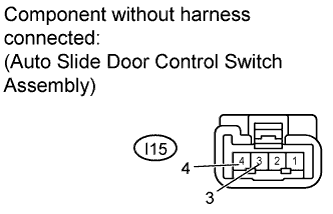
Measure the resistance of the switch.
Standard resistance Tester Connection Switch Condition Specified Condition I15-3 - I15-4 Not pushed 10 kΩ or higher I15-3 - I15-4 Pushed Below 1 Ω
NG
REPLACE AUTO SLIDE DOOR CONTROL SWITCH ASSEMBLY
OK
-
-
CHECK HARNESS AND CONNECTOR (POWER SLIDE DOOR ECU LH - AUTO SLIDE DOOR CONTROL SWITCH)
-
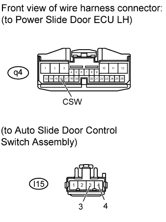
Measure the resistance.
Standard resistance Tester Connection Condition Specified Condition q4-16 (CSW) - I15-3 Always Below 1 Ω I15-4 - Body ground Always Below 1 Ω
NG
REPAIR OR REPLACE HARNESS OR CONNECTOR
OK
GO TO SYMPTOM SIMULATION Click here
-
-
INSPECT AUTO SLIDE DOOR MAIN SWITCH ASSEMBLY
-
Disconnect the I16 connector from the auto slide door main switch assembly.
-
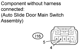
Measure the resistance of the switch.
Standard resistance Tester Connection Switch Condition Specified Condition I16-4 - I16-5 Not pushed Below 1 Ω I16-4 - I16-5 Pushed 10 kΩ or higher
NG
REPLACE AUTO SLIDE DOOR MAIN SWITCH ASSEMBLY
OK
-
-
CHECK HARNESS AND CONNECTOR (POWER SLIDE DOOR ECU LH - AUTO SLIDE DOOR MAIN SWITCH)
-
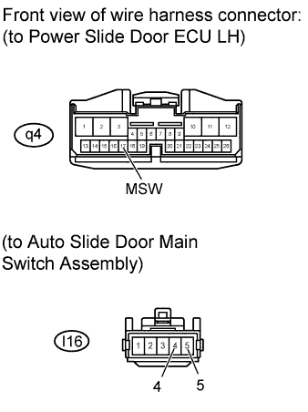
Measure the resistance.
Standard resistance Tester Connection Condition Specified Condition q4-17 (MSW) - I16-4 Always Below 1 Ω I16-5 - Body ground Always Below 1 Ω
NG
REPAIR OR REPLACE HARNESS OR CONNECTOR
OK
GO TO SYMPTOM SIMULATION Click here
-