POWER SLIDE DOOR SYSTEM, Diagnostic DTC:2-1

| DTC Code | DTC Name |
|---|---|
| 2-1 | Door Lock Half-latch Switch Malfunction |
DESCRIPTION
Code 2-1 is output when the power slide door lock assembly LH or power slide door lock assembly RH* (latch switch [half-latch]) is malfunctioning.
| DTC No. | DTC Detection Condition | Trouble Area |
|---|---|---|
| 2-1 |
|
|
-
*: for RH Side, w/ Power Slide Door
WIRING DIAGRAM
INSPECTION PROCEDURE
PROCEDURE
-
CLEAR DTC
-
Clear the DTC Click here.
NEXT 
-
-
CHECK FOR DTC
-
Check for DTC Click here.
Result Result Proceed to DTC is not output A DTC is output (for LH Side) B DTC is output (for RH Side, w/ Power Slide Door) C
B 
INSPECT POWER SLIDE DOOR LOCK ASSEMBLY LH Click here
C
INSPECT POWER SLIDE DOOR LOCK ASSEMBLY RH Click here
A 
USE SIMULATION METHOD TO CHECK Click here
-
-
INSPECT POWER SLIDE DOOR LOCK ASSEMBLY LH
-
Remove the power slide door lock assembly LH Click here.
-
Inspect the power slide door lock assembly LH Click here.
NG 
REPLACE POWER SLIDE DOOR LOCK ASSEMBLY LH Click here
OK
-
-
INSPECT NO. 2 REAR DOOR WIRE
-
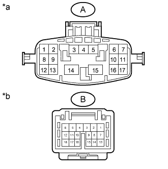
Text in Illustration *a No. 2 Rear Door Wire
(Door Control Relay Assembly Side)
*b No. 2 Rear Door Wire
(Power Slide Door Lock Assembly LH Side)
Disconnect the oq1 and po2 No. 2 rear door wire connectors.
-
Measure the resistance according to the value(s) in the table below.
Standard Resistance Tester Connection Condition Specified Condition A-11 - B-15 Always Below 1 Ω A-10 - B-16 Always Below 1 Ω
NG
REPLACE NO. 2 REAR DOOR WIRE Click here
OK
-
-
CHECK HARNESS AND CONNECTOR (POWER SLIDE DOOR LOCK ASSEMBLY LH - DOOR CONTROL RELAY ASSEMBLY)
-
Disconnect the p1 power slide door lock assembly LH connector.
-
Disconnect the q4 door control relay assembly connector.
-
Measure the resistance according to the value(s) in the table below.
Standard Resistance Tester Connection Condition Specified Condition q4-4 (HAF) - p1-3 (L1) Always Below 1 Ω q4-13 (OSG) - p1-8 (E2) Always Below 1 Ω q4-4 (HAF) or p1-3 (L1) - Body ground Always 10 kΩ or higher q4-13 (OSG) or p1-8 (E2) - Body ground Always 10 kΩ or higher
NG
REPAIR OR REPLACE HARNESS OR CONNECTOR
OK
REPLACE DOOR CONTROL RELAY ASSEMBLY Click here
-
-
INSPECT POWER SLIDE DOOR LOCK ASSEMBLY RH
-
Remove the power side door lock assembly RH Click here.
-
Inspect the power slide door lock assembly RH Click here.
NG
REPLACE POWER SLIDE DOOR LOCK ASSEMBLY RH Click here
OK
-
-
INSPECT REAR DOOR WIRE RH
-
Text in Illustration *a Rear Door Wire RH
(Door Control Relay Assembly Side)
*b Rear Door Wire RH
(Power Slide Door Lock Assembly RH Side)
Disconnect the ci1 and fc1 rear door wire RH connectors.
-
Measure the resistance according to the value(s) in the table below.
Standard Resistance Tester Connection Condition Specified Condition A-11 - B-15 Always Below 1 Ω A-10 - B-16 Always Below 1 Ω
NG
REPLACE REAR DOOR WIRE RH Click here
OK
-
-
CHECK HARNESS AND CONNECTOR (POWER SLIDE DOOR LOCK ASSEMBLY RH - DOOR CONTROL RELAY ASSEMBLY)
-
Disconnect the f1 power slide door lock assembly LH connector.
-
Disconnect the I4 door control relay assembly connector.
-
Measure the resistance according to the value(s) in the table below.
Standard Resistance Tester Connection Condition Specified Condition I4-4 (HAF) - f1-3 (HAF) Always Below 1 Ω I4-13 (OSG) - f1-8 (E1) Always Below 1 Ω I4-4 (HAF) or f1-3 (HAF) - Body ground Always 10 kΩ or higher I4-13 (OSG) or f1-8 (E1) - Body ground Always 10 kΩ or higher
NG
REPAIR OR REPLACE HARNESS OR CONNECTOR
OK
REPLACE DOOR CONTROL RELAY ASSEMBLY Click here
-