POWER SLIDE DOOR SYSTEM TERMINALS OF ECU

-
CHECK DOOR CONTROL RELAY (POWER SLIDE DOOR ECU LH)
-
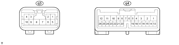
Disconnect the q3 and q4 ECU connectors.
-
Measure the voltage and resistance of each terminal of the wire harness side connectors.
Symbols (Terminal No.) Wiring Color Terminal Description Condition Specified Condition GND (q3-7) - Body ground W-B - Body ground Ground Always Below 1 Ω B (q3-8) - GND (q3-7) B-R - W-B Power supply Always 11 to 14 V HAF (q4-4) - SEL (q4-21) B - W-B Half latch switch input Half latch ON range → Expect half latch ON range Below 1 Ω → 10 kΩ or higher FUL (q4-5) - SEL (q4-21) Y - W-B Full latch switch input Full latch ON range → Over stroke Below 1 Ω → 10 kΩ or higher CPSW (q4-10) - GND (q3-7) R-Y - W-B Park/Neutral position switch input Ignition switch ON and shift lever P position → Expect P position 11 to 14 V → 0 V MPX1 (q4-8) - GND (q3-7) Y-G - W-B Power slide door handle switch input Slide door inside/outside handle not pulled → Pulled 10 kΩ or higher → Below 1 Ω IG (q4-9) - GND (q3-7) B-R - W-B Ignition power supply Ignition switch ON → OFF 11 to 14 V → 0 V ECUB (q4-11) - GND (q3-7) W-R - W-B Power supply Always 11 to 14 V OSG (q4-13) - Body ground BR - Body ground Ground Always Below 1 Ω OS (q4-14) - OSG (q4-13) G - BR Power slide door sensor input Power slide door sensor not pressed → Pressed Approx. 1 kΩ → Below 100 Ω DSW (q4-16) - GND (q3-7) B-Y - W-B Auto slide door control switch input Auto slide door control switch not pushed → Pushed 10 kΩ or higher → Below 1 Ω MSW (q4-17) - GND (q3-7) P - W-B Main switch input Auto slide door main switch not pushed → Pushed Below 1 Ω → 10 kΩ or higher POL (q4-18) - SEL (q4-21) L-R - W-B Pawl switch input Pawl switch ON → OFF Below 1 Ω → 10 kΩ or higher LMT (q4-19) - SEL (q4-21) L-W - W-B Initial position switch input Initial position switch ON → OFF Below 1 Ω → 10 kΩ or higher SEL (q4-21) - Body ground W-B - Body ground Ground Always Below 1 Ω DLSW (q4-22) - GND (q3-7) G-W - W-B Door unlock position switch input Slide door Lock → Unlock 10 kΩ or higher → Below 1 Ω SPD (q4-26) - SEL (q4-21) P-L - W-B Vehicle speed signal input IG ON
Drive wheel turned slowly
Pulse generation -
Reconnect the q3 and q4 ECU connectors.
-
Measure the voltage of each terminal of the wire harness side connectors.
Symbols (Terminal No.) Wiring Color Terminal Description Condition Specified Condition CL- (q3-6) - GND (q3-7) Y-R - W-B Power slide door clutch (-) output 1: Slide door fully opened and A*1switch turned ON →
2: Slide door in closing operation →
3: Slide door fully closed
1: 0 V →
2: 11 to 14 V ←→ 0 V pulse generation (Slide door in closing operation)
3: 0 V
DC+ (q3-5) - GND (q3-7) L - W-B Power slide door lock closer motor drive output (Close) 1: Slide door open and A*1switch turned OFF →
2: A*1switch turned ON →
3: Slide door in closing operation →
4: Not completely closed →
5: Operation completed (slide door closed)
1: 0 V →
2: 0 V →
3: 0 V →
4: 11 to 14 V →
5: 0 V
SD- (q3-3) - GND (q3-7) B - W-B Power slide door motor low open speed drive output Slide door in open operation, low speed range 11 to 14 V SD+ (q3-4) - GND (q3-7) L - W-B Power slide door motor high open speed drive output Slide door in open operation, high speed range 11 to 14 V CL+ (q3-2) - GND (q3-7) Y-B - W-B Power slide door clutch (+) output 1: Slide door fully closed and A*1switch turned ON →
2: Slide door in opening operation →
3: Slide door fully opened
1: 0 V →
2: 11 to 14 V →
3: 0 V
DC- (q3-1) - GND (q3-7) P - W-B Power slide door lock closer motor drive output (Release) 1: Slide door open →
2: Slide door inside/outside handle pulled →
3: Slide door in closing operation →
4: Not completely closed→
5: Operation completed (slide door closed) →
6: Motor in reverse rotation →
7: Operation completed (slide door closed)
1: 0 V →
2: 0 V →
3: 0 V →
4: 0 V →
5: 0 V →
6: 11 to 14 V →
7: 0 V
RACT (q3-12) - GND (q3-7) R-B - W-B Slide door lock release motor drive output 1: Slide door fully closed and A*1switch turned ON →
2: Slide door lock latch release operation →
3: Slide door in opening operation →
4: Slide door fully open
1: 0 V →
2: 11 to 14 V →
3: 0 V →
4: 0 V
BZR+ (q4-1) - GND (q3-7) W - W-B Power slide door warning buzzer output 1: Slide door fully closed (A*1switch turned OFF) →
2: A*1switch turned ON →
3: Slide door in opening operation →
4: Slide door fully open
1: 0 V →
2: 11 to 14 V (approx. 0.5 seconds) →
3: 0 V →
4: 0 V
BZR+ (q4-1) - GND (q3-7) W - W-B Power slide door warning buzzer output 1: Slide door fully closed →
2: Slide door inside/outside handle pulled →
3: Slide door in opening operation →
4: Slide door fully open
1: 0 V →
2: 11 to 14 V (approx. 0.1 seconds) →
3: 0 V →
4: 0 V
BZR+ (q4-1) - GND (q3-7) W - W-B Power slide door warning buzzer output 1: Slide door fully open (A*1switch turned OFF) →
2: A*1switch turned ON →
3: Slide door in closing operation →
4: Slide door fully closed
1: 0 V →
2: 11 to 14 V (approx. 0.5 seconds) →
3: Alternating between 11 to 14 V (approx. 0.1 seconds) →
4: 0 V
BZR+ (q4-1) - GND (q3-7) W - W-B Power slide door warning buzzer output 1: Slide door fully open →
2: Slide door inside/outside handle pulled →
3: Slide door in closing operation →
4: Slide door fully closed
1: 0 V →
2: 11 to 14 V (approx. 0.3 seconds) →
3: Alternating between 11 to 14 V (approx. 0.1 seconds) →
4: 0 V
DSV (q4-3) - DSG (q4-2) P - BR Power slide door drive unit pulse sensor power supply
Power slide door drive unit pulse sensor ground
IG ON 11 to 14 V DS2 (q4-23) - DSG (q4-2) B - BR Power slide door drive unit pulse sensor-2 signal input
Power slide door drive unit pulse sensor ground
1: Slide door fully closed →
2: Slide door in opening operation →
3: Slide door fully opened →
4: Slide door in closing operation →
5: Slide door fully closed
1: 0 V →
2: Alternating 11 to 14 V and 0 V →
3: 11 to 14 V →
4: Alternating 11 to 14 V and 0 V →
5: 0 V
DS1 (q4-24) - DSG (q4-2) LG - BR Power slide door drive unit pulse sensor-1 signal input
Power slide door drive unit pulse sensor ground
1: Slide door fully closed →
2: Slide door in opening operation →
3: Slide door fully opened →
4: Slide door in closing operation →
5: Slide door fully closed
1: 0 V →
2: Alternating 11 to 14 V and 0 V →
3: 11 to 14 V →
4: Alternating 11 to 14 V and 0 V →
5: 0 V
Tech Tips
*1: Auto slide door control switch
-
Use an oscilloscope to check the output voltages of the power slide door switch, buzzer and pulse sensor.
-
If the result is not as specified, the ECU may have a malfunction.
-
-
-
CHECK DOOR OPENING RELAY
-
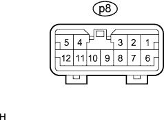
Disconnect the p8 ECU connector.
-
Measure the voltage and resistance of each terminal of the wire harness side connector.
Symbols (Terminal No.) Wiring Color Terminal Description Condition Specified Condition GND (p8-2) - Body ground W-B - Body ground Ground Always Below 1 Ω B (p8-6) - GND (p8-2) W - W-B Power supply Always 11 to 14 V -
Reconnect the p8 ECU connector.
-
Measure the voltage of each terminal of the wire harness side connector.
Symbols (Terminal No.) Wiring Color Terminal Description Condition Specified Condition L (p8-1) - E (p8-10) R - BR Slide door lock release motor output 1: Slide door lock fully closed →
2: A*1switch ON →
3: Slide door lock releasing operation →
4: Slide door lock fully released
1: 0 V →
2: 0 V →
3: 0 V →
4: 11 to 14 V → 0 V
UL (p8-3) - E (p8-10) B - BR Slide door lock release motor output 1: Slide door lock fully closed →
2: A*1switch ON →
3: Slide door lock releasing operation →
4: Slide door lock fully released
1: 0 V →
2: 0 V →
3: 11 to 14 V →
4: 0 V
CSW (p8-5) - E (p8-10) Y - BR Release position switch output Slide door fully open or closed → Slide door in opening operation or closing operation 11 to 14 V → 0 V → 11 to 14 V PSW (p8-12) - E (p8-10) L - BR Initial position switch output Slide door fully open or closed → Not completely open or closed 0 V → 11 to 14 V → 0 V Tech Tips
*1: Auto slide door control switch
-
If the result is not as specified, the ECU may have a malfunction.
-
-