LIGHTING SYSTEM TERMINALS OF ECU

-
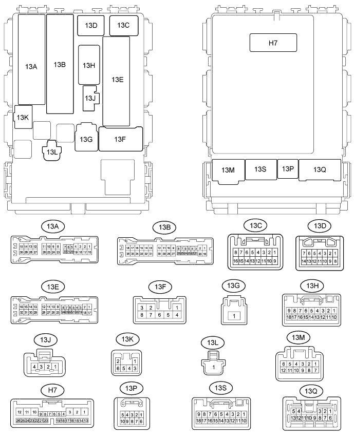
INSTRUMENT PANEL JUNCTION BLOCK (MAIN BODY ECU) [w/ Key Confine Prevention Function]
-
Disconnect the 13A, 13C, 13E, 13H, 13M, 5K, and H7 instrument panel junction block connectors.
-
Measure the voltage and resistance between the wire harness side connectors and body ground.
Terminal No.
(Symbol)
Wiring Color Terminal Description Condition Specified Condition 13A-18 (RRCY) - 13M-7 (GND)*1 W - W-B Rear door courtesy switch RH signal Rear door RH open Below 1 V 13A-18 (RRCY) - 13M-7 (GND)*1 W - W-B Rear door courtesy switch RH signal Rear door RH closed 11 to 14 V 13A-24 (RRCY) - 13M-7 (GND) W - W-B*3 Back door courtesy switch signal Back door open Below 1 V 13A-24 (RRCY) - 13M-7 (GND) W - W-B*3 Back door courtesy switch signal Back door closed 11 to 14 V 13A-30 (RRCY) - 13M-7 (GND)*1 W - W-B Rear door courtesy switch LH signal Rear door LH open Below 1 V 13A-30 (RRCY) - 13M-7 (GND)*1 W - W-B Rear door courtesy switch LH signal Rear door LH closed 11 to 14 V 13F-1 (BECU) - Body ground L - Body ground Battery power supply Always 11 to 14 V 13E-9 (DIM) - 13M-7 (GND) GR - W-B Headlight dimmer switch signal Headlight dimmer switch in tail position Below 1 V 13E-9 (DIM) - 13M-7 (GND) GR - W-B Headlight dimmer switch signal Headlight dimmer switch not in high or high flash position 11 to 14 V 13E-8 (DOMR) - 13M-7 (GND)*2 W - W-B Battery save system (interior light auto cut function) signal Battery save system (interior light auto cut function) not operating Below 1 V 13E-8 (DOMR) - 13M-7 (GND)*2 W - W-B Battery save system (interior light auto cut function) signal Battery save system (interior light auto cut function) operating 11 to 14 V 13E-10 (PCTY) - 13M-7 (GND) R - W-B Front passenger side door courtesy switch signal Front passenger side door open Below 1 V 13E-10 (PCTY) - 13M-7 (GND) R - W-B Front passenger side door courtesy switch signal Front passenger side door closed 11 to 14 V 13E-11 (DCTY) - 13M-7 (GND) G - W-B Driver side door courtesy switch signal Driver side door open Below 1 V 13E-11 (DCTY) - 13M-7 (GND) G - W-B Driver side door courtesy switch signal Driver side door closed 11 to 14 V 13M-7 (GND) - Body ground W-B - Body ground Ground Always Below 1 Ω 13E-20 (HRLY) - 13M-7 (GND) R - W-B HEAD relay drive signal Headlight dimmer switch off 11 to 14 V 13E-20 (HRLY) - 13M-7 (GND) R - W-B HEAD relay drive signal Headlight dimmer switch on Below 1 V 13H-3 (TRLY) - 13M-7 (GND) G - W-B Headlight dimmer switch signal Headlight dimmer switch off 11 to 14 V 13H-3 (TRLY) - 13M-7 (GND) G - W-B Headlight dimmer switch signal Headlight dimmer switch TAIL Below 1 V 13K-2 (ILE) - 13M-7 (GND) LG - W-B*3
Y - W-B*4
Map light light signal Map light off using illuminated entry system 11 to 14 V 13K-2 (ILE) - 13M-7 (GND) LG - W-B*3
Y - W-B*4
Map light light signal Map light on using illuminated entry system Below 1 V 13H-5 (ILE) - 13M-7 (GND)*5 L - W-B Ignition key cylinder light signal*9
Transponder key light signal*10
Ignition key cylinder light off using illuminated entry system*9
Transponder key light off using illuminated entry system*10
11 to 14 V 13H-5 (ILE) - 13M-7 (GND)*5 L - W-B Ignition key cylinder light signal*9
Transponder key light signal*10
Ignition key cylinder light on using illuminated entry system*9
Transponder key light on using illuminated entry system*10
Below 1 V H7-10 (CLTB) - 13M-7 (GND)*6 P - W-B Automatic light control sensor signal Always 11 to 14 V H7-11 (CLTS) - 13M-7 (GND)*6 B - W-B Automatic light control sensor signal Ignition switch off Below 1 V H7-11 (CLTS) - 13M-7 (GND)*1 B - W-B Automatic light control sensor signal Ignition switch ON
Headlight dimmer switch AUTO
Pulse generation
(See waveform 1)
H7-12 (CLTE) - 13M-7 (GND)*6 W - W-B Ground Always Driver side door unlock detection switch signal H7-13 (A) - 13M-7 (GND)*6 BE - W-B Headlight dimmer switch signal Headlight dimmer switch off 11 to 14 V H7-13 (A) - 13M-7 (GND)*6 BE - W-B Headlight dimmer switch signal Headlight dimmer switch AUTO Below 1 V H7-15 (HEAD) - 13M-7 (GND) R - W-B Headlight dimmer switch signal Headlight dimmer switch off 11 to 14 V H7-15 (HEAD) - 13M-7 (GND) R - W-B Headlight dimmer switch signal Headlight dimmer switch HEAD Below 1 V H7-17 (FFOG) - 13M-7 (GND)*7 P - W-B Front fog light switch input Front fog light switch off 11 to 14 V H7-17 (FFOG) - 13M-7 (GND)*7 P - W-B Front fog light switch input Front fog light switch on Below 1 V H7-16 (RFOG) - 13M-7 (GND)*8 R - W-B Rear fog light switch input Rear fog light switch off 11 to 14 V H7-16 (RFOG) - 13M-7 (GND)*8 R - W-B Rear fog light switch input Rear fog light switch on Below 1 V H7-18 (HF) - 13M-7 (GND) B - W-B Headlight dimmer switch high flash signal input Headlight dimmer switch not in high flash position 11 to 14 V H7-18 (HF) - 13M-7 (GND) B - W-B Headlight dimmer switch high flash signal input Headlight dimmer switch in high flash position Below 1 V H7-19 (HU) - 13M-7 (GND) GR - W-B Headlight dimmer switch high signal input Headlight dimmer switch in low position 11 to 14 V H7-19 (HU) - 13M-7 (GND) GR - W-B Headlight dimmer switch high signal input Headlight dimmer switch in high position Below 1 V 13C-8 (FFGO) - 13M-7 (GND)*7 GR - W-B Front fog light signal output Front fog light switch off 11 to 14 V 13C-8 (FFGO) - 13M-7 (GND)*7 GR - W-B Front fog light signal output Headlight dimmer switch in tail position and front fog light switch on Below 1 V 13C-16 (RFGO) - 13M-7 (GND)*8 Y - W-B Rear fog light signal output Rear fog light switch off 11 to 14 V 13C-16 (RFGO) - 13M-7 (GND)*8 Y - W-B Rear fog light signal output Headlight dimmer switch in tail position and rear fog light switch on Below 1 V If the result is not as specified, there may be a malfunction on the wire harness side.
*1: for 5-Door
*2: w/ Key Confine Prevention Function
*3: w/ Personal Light Assembly
*4: w/o Personal Light Assembly
*5: w/o Smart Entry and Start System
*6: w/ Automatic Light Control System
*7: w/ Front Fog Light
*8: w/ Rear Fog Light
*9: w/o Engine Immobiliser System
*10: w/ Engine Immobiliser System
-
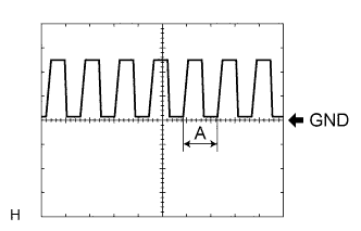
Waveform 1
Item Description Terminal H7-11 (CLTS) - 13M-7 (GND) Gauge 5 V/DIV, 5 ms/DIV Condition Ignition switch ON, Headlight dimmer switch AUTO Tech Tips
If the ambient light becomes brighter, width A becomes narrower.
-
-
HEADLIGHT LEVELING ECU ASSEMBLY (for LED Headlight)
-
Disconnect the A39 headlight leveling ECU connector.

-
Measure the voltage and resistance between the wire harness side connectors and body ground.
Terminal No.
(Symbol)
Wiring Color Terminal Description Condition Specified Condition A39-1 (IG) - A39-9 (E1) B - W-B Ignition power supply Ignition switch off Below 1 V A39-1 (IG) - A39-9 (E1) B - W-B Ignition power supply Ignition switch ON 11 to 14 V A39-2 (RLEW) - A39-9 (E1) G - W-B LED headlight signal input Headlight dimmer switch off Below 1 V A39-2 (RLEW) - A39-9 (E1) G - W-B LED headlight signal input Headlight dimmer switch in head position Pulse generation A39-3 (LLEW) - A39-9 (E1) L - W-B LED headlight signal input Headlight dimmer switch off Below 1 V A39-3 (LLEW) - A39-9 (E1) L - W-B LED headlight signal input Headlight dimmer switch in head position Pulse generation A39-4 (HDLP) - A39-9 (E1) R - W-B Low beam headlight signal input Low beam headlights on Below 1 V A39-4 (HDLP) - A39-9 (E1) R - W-B Low beam headlight signal input Low beam headlights off 11 to 14 V A39-9 (E1) - Body ground W-B - Body ground Ground Always Below 1 Ω A39-10 (RH+) - A39-9 (E1) R - W-B Headlight leveling motor RH power supply Ignition switch off Below 1 V A39-10 (RH+) - A39-9 (E1) R - W-B Headlight leveling motor RH power supply Ignition switch ON 11 to 14 V A39-11 (LH+) - A39-9 (E1) W - W-B Headlight leveling motor LH power supply Ignition switch off Below 1 V A39-11 (LH+) - A39-9 (E1) W - W-B Headlight leveling motor LH power supply Ignition switch ON 11 to 14 V A39-12 (SBR) - A39-21 (SGR) BE - G Rear height control sensor power supply Ignition switch off Below 1 V A39-12 (SBR) - A39-21 (SGR) BE - G Rear height control sensor power supply Ignition switch ON 4.75 to 5.25 V A39-17 (RHT) - A39-9 (E1) V - W-B Headlight leveling motor RH operation signal input With low beam headlights on, vehicle height not changed Below 1 V A39-17 (RHT) - A39-9 (E1) V - W-B Headlight leveling motor RH operation signal input With low beam headlights on, vehicle height changed and maintained for more than 3 seconds 1 to 14.4 V A39-18 (LHT) - A39-9 (E1) Y - W-B Headlight leveling motor LH operation signal input With low beam headlights on, vehicle height not changed Below 1 V A39-18 (LHT) - A39-9 (E1) Y - W-B Headlight leveling motor LH operation signal input With low beam headlights on, vehicle height changed and maintained for more than 3 seconds 1 to 14.4 V A39-19 (SHRL) - A39-21 (SGR) L - G Rear height control sensor signal input Ignition switch off Below 1 V A39-19 (SHRL) - A39-21 (SGR) L - G Rear height control sensor signal input Ignition switch ON 0.5 to 4.5 V A39-21 (SGR) - A39-9 (E1) G - W-B Rear height control sensor ground Always Below 1 Ω A39-23 (RH-) - A31-9 (E1) L - W-B Headlight leveling motor RH ground Always Below 1 Ω A39-24 (LH-) - A39-9 (E1) LG - W-B Headlight leveling motor LH ground Always Below 1 Ω If the result is not as specified, there may be a malfunction on the wire harness side.
-
-
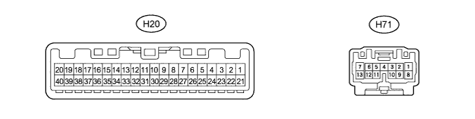
COMBINATION METER ASSEMBLY
-
Disconnect the H20 and H71 combination meter connectors.
-
Measure the voltage and resistance between the wire harness side connectors and body ground.
Terminal No.
(Symbol)
Wiring Color Terminal Description Condition Specified Condition H20-2 (IG+) - Body ground B - Body ground Ignition power supply Ignition switch off Below 1 V H20-2 (IG+) - Body ground B - Body ground Ignition power supply Ignition switch ON 11 to 14 V H20-21 (E1) - Body ground W-B - Body ground Ground Always Below 1 Ω H20-25 (SW) - Body ground GR - Body ground Turn signal switch (right turn or left turn position) signal input Ignition switch ON
Turn signal switch off
11 to 14 V H20-25 (SW) - Body ground GR - Body ground Turn signal switch (right turn or left turn position) signal input Ignition switch ON
Turn signal switch in right turn or left turn position
Below 1 V H20-26 (ER) - Body ground Y - Body ground Turn signal switch (right turn position) signal input Ignition switch ON
Turn signal switch off
11 to 14 V H20-26 (ER) - Body ground Y - Body ground Turn signal switch (right turn position) signal input Ignition switch ON
Turn signal switch in right turn position
Below 1 V H20-27 (EL) - Body ground B - Body ground Turn signal switch (left turn position) signal input Ignition switch ON
Turn signal switch off
11 to 14 V H20-27 (EL) - Body ground B - Body ground Turn signal switch (left turn position) signal input Ignition switch ON
Turn signal switch in left turn position
Below 1 V H20-28 (HAZ) - Body ground W - Body ground Hazard warning switch signal Hazard warning switch off 11 to 14 V H20-28 (HAZ) - Body ground W - Body ground Hazard warning switch signal Hazard warning switch on Below 1 V H20-38 (DRLE) - Body ground* Y - Body ground Daytime running light system drive output Daytime running light system not operating 11 to 14 V H20-38 (DRLE) - Body ground* Y - Body ground Daytime running light system drive output Daytime running light system operating Below 1 V H71-1 (B) - Body ground L - Body ground Battery power supply Always 11 to 14 V H71-7 (LR) - Body ground R - Body ground RH turn signal light signal output Ignition switch ON
RH turn signal light off
Below 1 V H71-7 (LR) - Body ground R - Body ground RH turn signal light signal output Ignition switch ON
RH turn signal light blinking
Below 1 V ←→ 11 to 14 V H71-13 (LL) - Body ground L - Body ground LH turn signal light signal output Ignition switch ON
LH turn signal light off
Below 1 V H71-13 (LL) - Body ground L - Body ground LH turn signal light signal output Ignition switch ON
LH turn signal light blinking
Below 1 V ←→ 11 to 14 V If the result is not as specified, there may be a malfunction on the wire harness side.
*: w/ Daytime Running Light
-
-
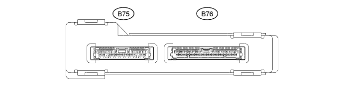
CERTIFICATION ECU (SMART KEY ECU ASSEMBLY) [w/ Smart Entry and Start System]
-
Disconnect the B75 certification ECU connector.
-
Measure the voltage and resistance between the wire harness side connectors and body ground.
Terminal No.
(Symbol)
Wiring Color Terminal Description Condition Specified Condition B75-1 (+B) - Body ground L - Body ground Battery power supply Always 11 to 14 V B75-10 (E) - Body ground W-B - Body ground Ground Always Below 1 Ω B75-19 (SWIL) - B75-24 (AGND) P - V Engine switch illumination operation signal Engine switch illumination on 11 to 14 V B75-19 (SWIL) - B75-24 (AGND) P - V Engine switch illumination operation signal Engine switch illumination off Below 1 V If the result is not as specified, there may be a malfunction on the wire harness side.
-